 Frese di precisione,Utensili da taglio per la lavorazione CNC di ogni materiale

Selected Standard Metric Configurations
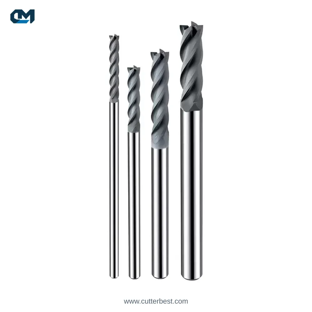
The table below lists selected sizes for our diamond coated corner radius end mills for graphite. All dimensions are in millimeters. If you need a configuration that isn’t shown, send us your required dimensions so we can check the catalog.
| Cutting Dia D | Raggio d'angolo R | Lunghezza del taglio L1 | Lunghezza effettiva L2 | Lunghezza totale L | Shank Dia. D | Flauti |
|---|---|---|---|---|---|---|
| 0.5 | 0.05 | 1 | 4 | 50 | 4 | 2 |
| 1 | 0.1 | 3 | 10 | 50 | 4 | 2 |
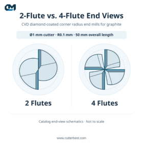
| 1 | 0.1 | 3 | 10 | 50 | 4 | 4 |
| 1.5 | 0.1 | 3 | 7 | 50 | 4 | 4 |
| 2 | 0.2 | 6 | 10 | 60 | 4 | 4 |
| 2 | 0.2 | 6 | 15 | 75 | 4 | 4 |
| 3 | 0.2 | 6 | 10 | 50 | 4 | 4 |
| 3 | 0.2 | 10 | — | 75 | 3 | 4 |
| 4 | 0.5 | 12 | — | 75 | 4 | 4 |
| 6 | 1 | 25 | — | 100 | 6 | 4 |
| 8 | 0.3 | 25 | — | 75 | 8 | 4 |
| 10 | 1 | 40 | — | 200 | 10 | 4 |
| 12 | 0.5 | 30 | — | 100 | 12 | 4 |
A dash indicates that the catalog does not list a separate L2 value for that configuration.
Tool Drawing and Dimension Symbols
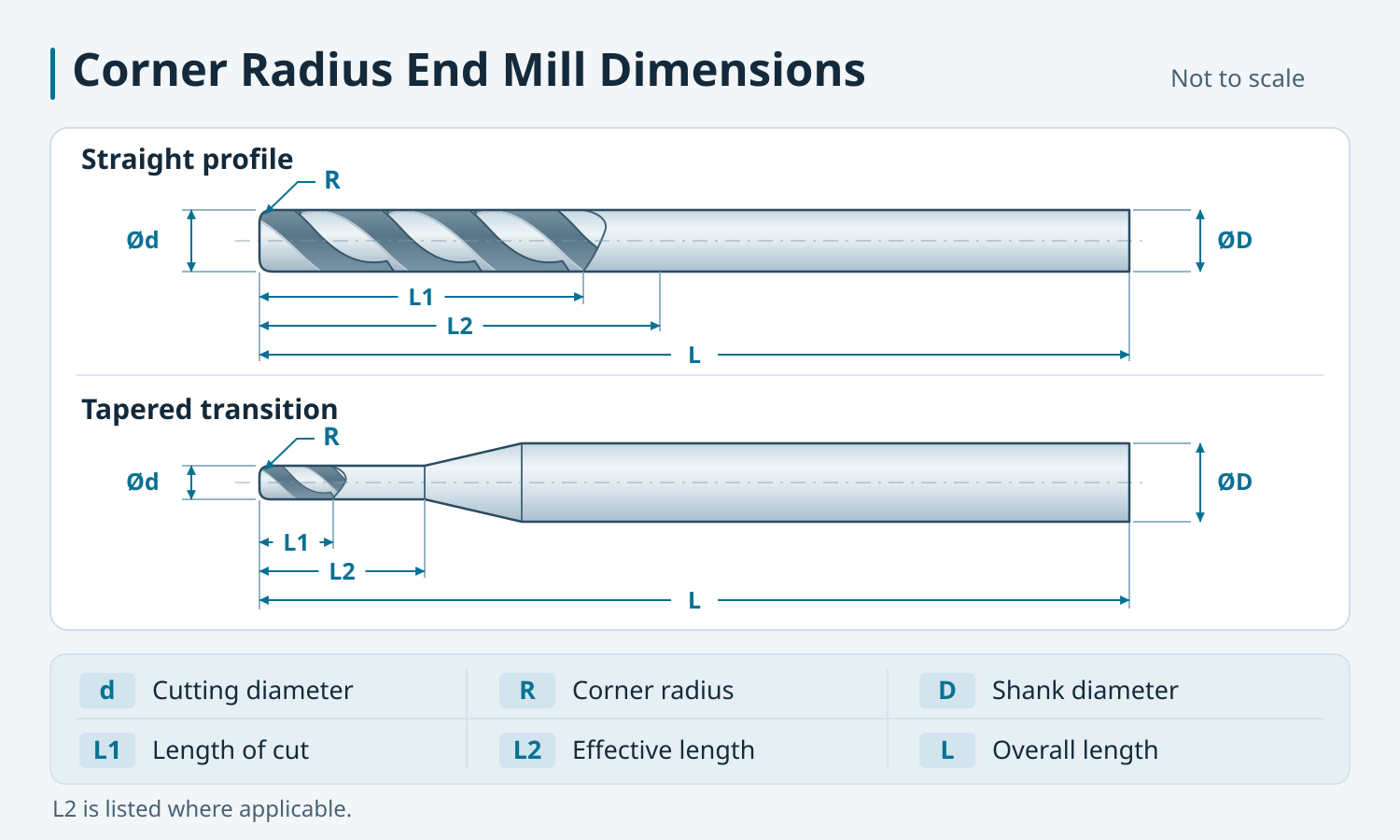
- D is the cutting diameter, E D is the shank diameter.
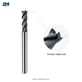
- R is the radius at the corner of the cutting end.
- L1 is the length of cut. L2 is the effective length measured from the tool tip to the point marked on the applicable drawing. On the profile with a tapered transition, L2 ends where the taper begins.
- L is the overall tool length.
Corner Radius End Mills for Graphite Machining
Graphite Electrodes and Mold Features
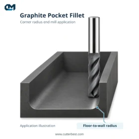
Use this geometry for flat-bottom pockets in graphite electrodes and recesses in graphite mold components where the part drawing calls for a radius between the floor and sidewall.
The tool’s corner radius R applies to that floor-to-wall transition. Check inside corners in the top view separately, where the cutter diameter and toolpath determine the achievable contour.
For guidance on choosing tools for different operations, vedi il nostro graphite roughing and finishing guide. For other tool profiles, see the Gamma di frese con rivestimento diamantato CVD.
How to Select a Standard Configuration
Match the Cutter Diameter and Corner Radius
Start with the radius specified on the part drawing. Then check that the cutting diameter fits the feature and allows the planned toolpath. Use the table to find the catalog rows that match both dimensions.
Check Length, Shank Diameter and Clearance
Choose a length of cut that covers the area the cutting edges need to machine. Check that the shank fits your holder and that the tool and holder clear the workpiece at the planned stickout. Establish usable machining depth from the setup and part geometry.
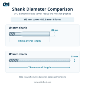
The table shows two Ø3 mm, R0,2 mm, 4-flauto examples. The configuration with a 50 lunghezza totale mm has a Ø4 mm shank, UN 6 mm lunghezza di taglio e a 10 mm effective length. The configuration with a 75 lunghezza totale mm has a Ø3 mm shank and a 10 lunghezza di taglio mm. The catalog gives no separate L2 value for the 75 mm configuration.
Domande frequenti
Can I send a drawing in inches?
Sì. Keep the original units on your drawing. We can review the dimensions and confirm the metric tool configuration with you before ordering.
What if the corner radius has a tight tolerance?
Mark the required tolerance next to R on the drawing. We’ll review it for the specific configuration and confirm what we can quote.
Request a Quote For diamond coated corner radius end mills
Standard Size Inquiries
Send your required cutting diameter, corner radius and quantity. Include any fixed length, shank diameter or flute count requirements. If you need several sizes, list each size and quantity on a separate line.
Drawing-Based Custom Inquiries
Send a tool drawing or a sketch of the graphite feature. Mark the required radius and any reach or clearance constraints so we can review the tool geometry.
Request a quote for CVD diamond-coated corner radius end mills di emailing sales@cutterbest.com O chatting with us on WhatsApp.