 精密フライスカッター,あらゆる材料を加工するCNC用の切削工具

Ball nose end mill stepover directly affects the theoretical scallop, or cusp, left between adjacent finishing passes. A smaller stepover reduces this geometric residual height, while a larger stepover reduces the number of passes needed to cover the same area.
しかし, there is no universal stepover percentage that works for every finishing operation. Tool radius, target scallop height, surface geometry, CAM strategy, machine behavior, and the required final surface all influence the practical setting.
This guide focuses on the geometry behind stepover and scallop height so you can calculate a useful starting point without confusing theoretical surface geometry with measured surface roughness.
簡単な回答: Ball Nose Stepover and Scallop Height
For a full ball nose end mill with radius R and adjacent toolpaths separated by stepover s, the ideal geometric scallop height h on a flat surface is:
Exact scallop height:
h = R − √(R² − (s/2)²)
If you already know the maximum theoretical scallop height you want, rearrange the formula to calculate stepover:
Stepover from target scallop height:
s = 2√(2Rh − h²)
For relatively small stepovers compared with the ball diameter, a useful approximation is:
Small-step approximation:
h ≈ s² / (8R)
The exact equation describes the ideal geometric scallop between parallel ball-end passes on a flat surface. It does not include cutting dynamics or workpiece surface curvature.
したがって, these calculations provide a geometric starting point rather than a guaranteed measured surface finish.
What Is Stepover in Ball Nose Milling?
Stepover is the lateral distance between two adjacent toolpaths. In ball nose finishing, it controls how closely the cutter passes overlap as the tool moves across the surface.
A larger stepover leaves a larger theoretical cusp between adjacent paths. 対照的に, reducing the stepover lowers the theoretical scallop but increases the number of passes required to cover the same machining area.
Stepover is different from stepdown. It describes the lateral spacing between neighboring toolpaths, while stepdown describes the depth between machining levels.
Stepover as a Distance and as a Percentage
CAM systems and machining discussions often express stepover either as an absolute distance or as a percentage of the tool diameter.
For a full ball nose end mill:
Stepover % = (s / D) × 100%
where:
- s = stepover distance
- D = ball nose cutting diameter
- R = ball radius
- for a standard full ball end, D=2R
例えば, ある 0.5 mm stepover with a Ø10 mm ball nose cutter equals:
0.5 / 10 × 100% = 5%
しかし, this percentage is only another way to describe the toolpath spacing. It is not a universal recommendation.
あ 5%, 10%, 又は 20% stepover can produce very different theoretical scallop heights when tool diameter changes.
What Are Scallop Height and Cusp Height?
Scallop height is the theoretical geometric residual height left between adjacent cutter passes.
用語 cusp height is also commonly used for this geometric feature. このガイドの内容, scallop height and cusp height describe the residual height created between neighboring ball nose toolpaths.
For finishing calculations, the important variables are:
- tool radius;
- lateral stepover;
- surface geometry.
A smaller theoretical scallop normally creates a finer geometric path pattern. しかし, scallop height does not directly tell you the measured surface roughness of the finished part.
That distinction becomes especially important when an engineering drawing specifies Ra.
Ball Nose Stepover Geometry
The basic ball nose stepover formula comes from a cross-section through two adjacent cutter paths on an ideal flat surface.
Each cutter profile has radius R. The distance between the two path centers is s, so the midpoint lies s/2 from each path center. The remaining height above the reference surface is the scallop height h.
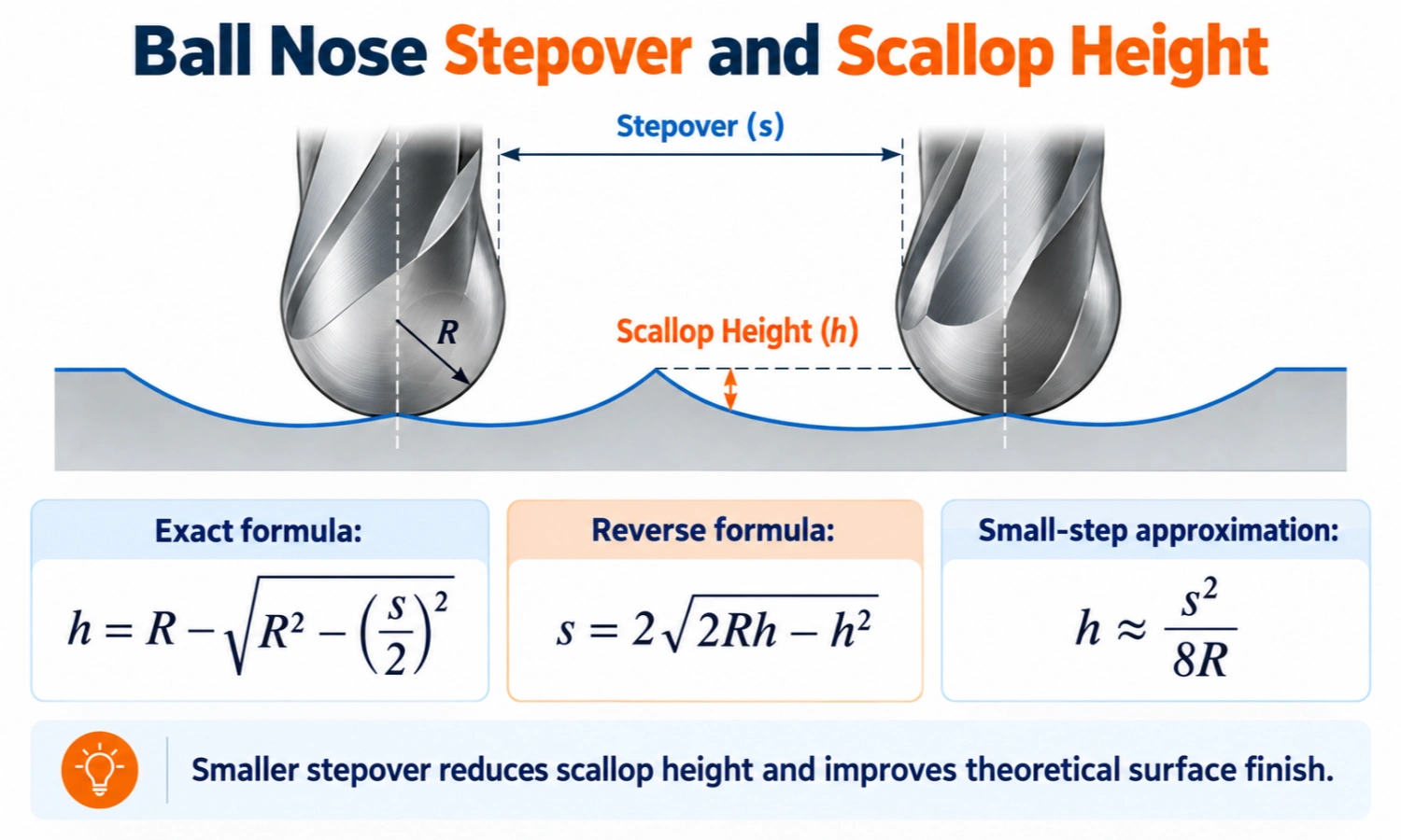
Exact Scallop Height Formula
For the ideal geometry:
h = R − √(R² − (s/2)²)
where:
- h = theoretical scallop or cusp height;
- R = ball nose radius;
- D = full ball nose diameter, where D = 2R;
- s = lateral spacing between adjacent parallel toolpaths.
All dimensions must use the same unit.
For this geometric model:
- R > 0
- 0 ≤ s ≤ 2R
This formula is exact for the ideal geometric scallop between parallel ball-end passes on a flat surface. It assumes an ideal ball profile and does not include tool runout, 着る, 偏向, material deformation, 振動, or other cutting effects.
Small-Step Approximation
When stepover is small relative to the ball diameter, the exact equation can be approximated as:
h ≈ s² / (8R)
This is an approximation, not a replacement for the exact formula.
A useful way to judge the approximation is to compare stepover with diameter:
s / D ≪ 1
As the relative stepover increases, the approximation gradually underestimates the exact geometric scallop.
例えば, using a Ø10 mm / R5 mm ball nose:
| Stepover Ratio | Exact Scallop | Approximation | Underestimation |
|---|---|---|---|
| 10% of D | 25.063 µm | 25.000 µm | about 0.25% |
| 20% of D | 101.021 µm | 100.000 µm | about 1.01% |
These percentages illustrate mathematical approximation error, not recommended machining stepovers.
したがって, this guide uses the exact equation for worked calculations and reference tables.
A Limitation on Curved 3D Surfaces
The flat-surface equation should not be treated as an exact result for every 3D contour.
On a curved surface, a fixed planar or XY stepover does not necessarily produce a constant scallop height. Local surface curvature and the actual spacing of toolpaths along the surface can change the resulting cusp.
CAM constant-scallop strategies can control this more effectively by adjusting toolpath spacing according to the surface.
This guide does not attempt to model full 3D surface curvature mathematically. その代わり, use the flat-surface equation as a geometric planning tool and verify the final CAM strategy on the actual part geometry.
How to Calculate Stepover from a Target Scallop Height
In finishing work, the reverse question is often more useful:
If I know the theoretical scallop height I want, what stepover should I use?
Rearranging the exact equation gives:
s = 2√(2Rh − h²)
where:
- s = calculated stepover;
- R = ball radius;
- h = target theoretical scallop height.
For the ideal geometric model:
0 ≤ h ≤ R
If h represents a maximum planning value, the calculated stepover provides the corresponding geometric spacing limit under the ideal flat-surface model. しかし, it does not guarantee a particular measured Ra or surface appearance.
Worked Metric Example
Suppose you are planning a finishing pass with:
Ball nose diameter: Ø10mm
ボール半径: R = 5 ミリメートル
Target theoretical scallop: h = 0.01 mm = 10 µm
使用:
s = 2√(2Rh − h²)
Substitute the values:
s = 2√(2 × 5 × 0.01 − 0.01²) = 2√0.0999 ≈ 0.632 ミリメートル
したがって:
Calculated stepover ≈ 0.632 ミリメートル
As a percentage of the Ø10 mm cutter:
0.632139 / 10 × 100 ≈ 6.32%
So the calculated stepover is approximately:
0.632 ミリメートル, 又は 6.32% of tool diameter.
これ 6.32% value is the mathematical result for this example. It is not a universal recommended stepover.
同じく, a theoretical scallop height of 10 µm does not mean the machined surface will have ラ 10 µm.
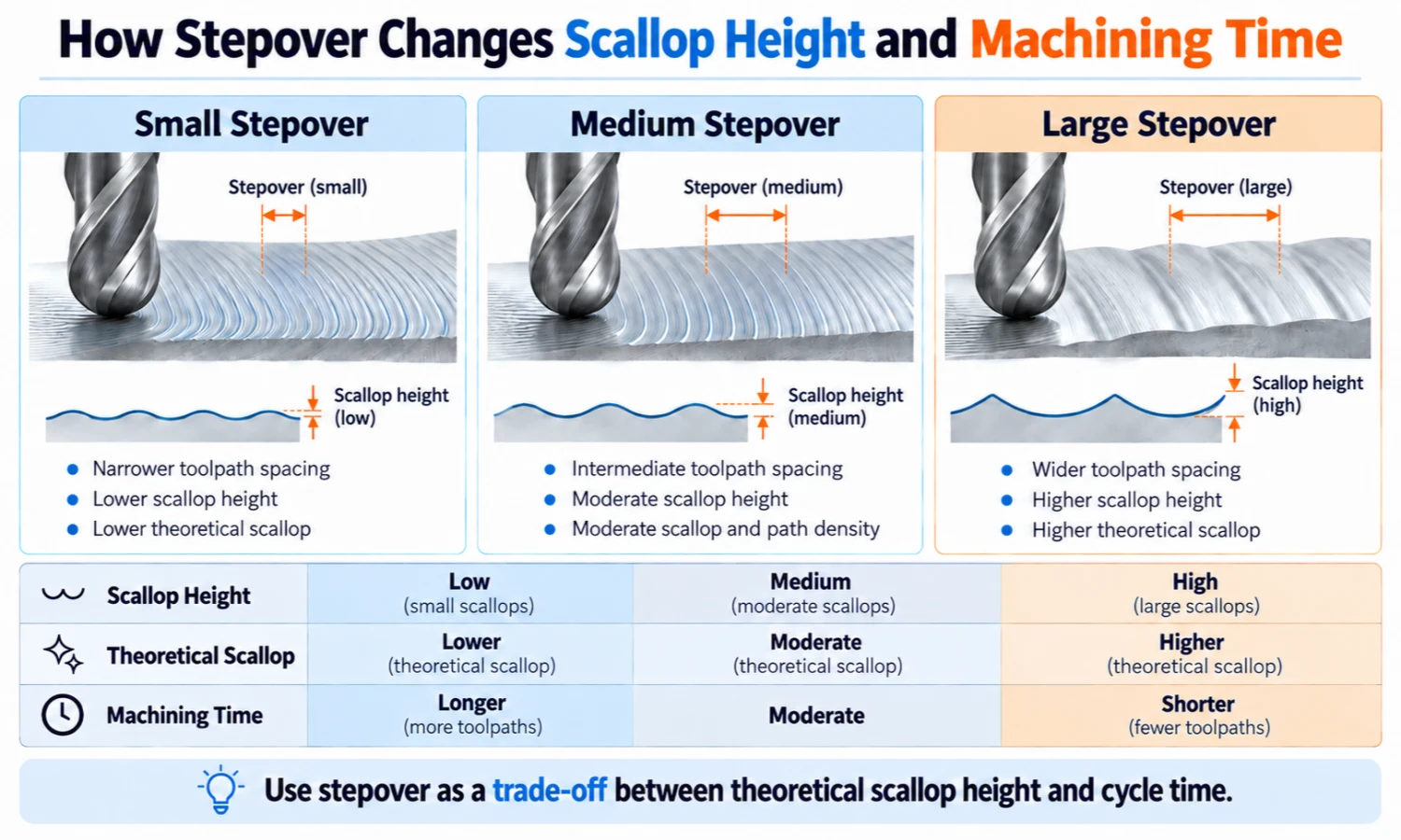
Metric Stepover and Scallop Height Reference Table
The following tables use the exact scallop height formula.
They are geometric calculation examples rather than universal machining recommendations.
Same Tool Size, Different Stepovers
This first comparison keeps the tool fixed at Ø10mm / R5 mm so you can see the direct effect of changing stepover.
| 工具径 / 半径 | Stepover | Stepover % of D | Exact Scallop Height |
|---|---|---|---|
| Ø10 / R5 | 0.25 ミリメートル | 2.50% | 1.563 µm |
| Ø10 / R5 | 0.50 ミリメートル | 5.00% | 6.254 µm |
| Ø10 / R5 | 0.75 ミリメートル | 7.50% | 14.082 µm |
| Ø10 / R5 | 1.00 ミリメートル | 10.00% | 25.063 µm |
1 µm = 0.001 ミリメートル.
Notice that scallop height does not increase linearly with stepover. Doubling the stepover increases the geometric residual by more than two times.
したがって, relatively small changes in finishing stepover can produce meaningful changes in theoretical cusp height.
Same Absolute Stepover, Different Ball Radii
The next comparison holds the absolute stepover at 0.50 ミリメートル and changes the tool radius.
| 工具径 / 半径 | Stepover | Stepover % of D | Exact Scallop Height |
|---|---|---|---|
| Ø4 / R2 | 0.50 ミリメートル | 12.50% | 15.687 µm |
| Ø6 / R3 | 0.50 ミリメートル | 8.33% | 10.435 µm |
| Ø8 / R4 | 0.50 ミリメートル | 6.25% | 7.820 µm |
| Ø12 / R6 | 0.50 ミリメートル | 4.17% | 5.211 µm |
This comparison is intentionally based on the same absolute stepover distance.
Do not interpret it as a comparison at the same stepover percentage.
How Ball Nose Radius Affects Scallop Height
Ball radius changes the geometric relationship between adjacent finishing passes.
At the same absolute stepover distance, a larger ball radius produces a lower theoretical scallop height.
例えば, the table above uses the same 0.50 mm stepover for R2, R3, R4, and R6 tools. As radius increases, the calculated cusp becomes progressively smaller.
The reverse is also useful when planning a finish:
For the same target theoretical scallop height, a larger ball radius allows a larger absolute stepover.
しかし, this does not mean that the largest available cutter is automatically the best choice.
Tool diameter and radius still need to fit the part geometry, 空洞, local curvature, access conditions, and other machining requirements.
For broader tool-selection factors, 見る ボールエンドミルの選び方.
How Ball Nose End Mill Stepover Affects Scallop Height and Machining Time
Reducing stepover lowers the theoretical scallop height, but it also increases the number of toolpaths needed to cover the same surface.
This creates one of the main finishing trade-offs.
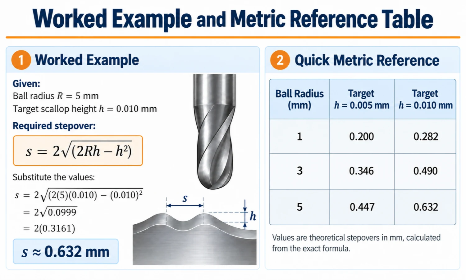
Stepover vs Scallop vs Machining Time Comparison
| Stepover Change | Theoretical Scallop | Finishing Passes | Cycle-Time Tendency |
|---|---|---|---|
| Increase stepover | より高い | Fewer | Usually shorter |
| Decrease stepover | より低い | もっとその | Usually longer |
For the same machining area and a comparable toolpath strategy, reducing stepover generally increases the number of finishing passes.
しかし, do not assume that halving stepover will always double cycle time.
Why Machining Time Does Not Scale Perfectly with Stepover
Actual cycle time depends on more than the number of adjacent passes.
Other factors include:
- machining-area geometry;
- actual toolpath length;
- toolpath strategy;
- linking moves;
- acceleration and deceleration;
- boundary trimming;
- path overlaps;
- retract and return moves;
- rest-machining regions;
- machine motion.
したがって, scallop calculations can help you understand the surface-versus-path-density trade-off, but CAM simulation gives a better estimate of actual cycle time.
Scallop Height Is Not Surface Roughness Ra
One of the most important distinctions in ball nose finishing is:
Calculated scallop height is not the same as measured surface roughness Ra.
The scallop equation predicts an ideal geometric residual between adjacent toolpaths.
ラ, 対照的に, measures the arithmetic average of deviations in an actual surface profile under defined measurement conditions.
A small calculated cusp may contribute to a smoother geometric toolpath pattern, but it does not guarantee a specific measured Ra.
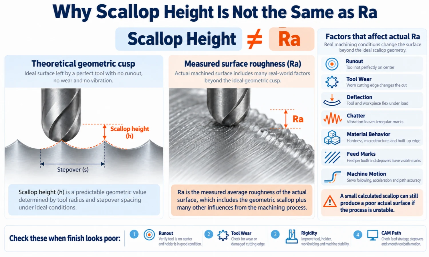
Geometric Scallop Height vs Measured Ra
Theoretical scallop height depends mainly on:
- ボールの半径;
- stepover;
- the geometric relationship between adjacent paths;
- local surface geometry.
Measured surface roughness can also depend on:
- 工具振れ;
- 工具の摩耗;
- 工具のたわみ;
- chatter or structural vibration;
- workholding stability;
- material behavior;
- material adhesion or built-up edge;
- チップ再切断;
- feed-related surface marks;
- machine motion;
- toolpath interpolation;
- local surface curvature;
- measurement direction and measurement method.
このため, there is no universal rule such as:
Ra = scallop height / 4
that can reliably convert a theoretical ball nose scallop into the Ra value of a real machined surface.
Specific idealized surface profiles can have mathematical roughness relationships, but those relationships should not be treated as universal conversions for actual machining.
Why the Surface Can Still Look Poor with a Small Calculated Scallop
A small calculated cusp only tells you that the ideal cross-path geometry is fine.
If the actual surface still shows visible marks or inconsistent texture, the dominant problem may lie somewhere else.
| Surface Observation | 考えられる原因 | 確認すべきこと |
|---|---|---|
| Regular ridges between adjacent passes | Stepover is large relative to the target geometric cusp | Tool radius, stepover, and calculated h |
| Uneven marks despite a small calculated h | なくなる, 工具の摩耗, 偏向, or setup instability | 道具, ホルダー, ワークホールディング, そしてセットアップ |
| Repeating vibration marks | Chatter or structural instability | 機械, ホルダー, 工具オーバーハング, and setup stability |
| Smearing or tearing | Material adhesion, edge condition, or cutting-condition issue | Tool condition and workpiece response |
| Directional marks along the toolpath | Feed-related surface texture | Distinguish along-path marks from cross-path scallops |
| Finish changes across a 3D surface | Local curvature or actual path spacing changes | Surface geometry and CAM toolpath strategy |
The purpose of this table is to identify whether the problem is primarily geometric or whether another machining factor deserves attention.
Detailed RPM, 切断速度, 歯当たりの送り, chip load, effective cutting diameter, and speed compensation belong to a separate feeds-and-speeds analysis.
How to Choose a Practical Ball Nose Stepover
A practical ball nose end mill stepover starts with geometry, but the final setting also depends on the actual machining conditions.
Use the following process instead of applying one universal percentage.
ステップ 1: Identify the Actual Finish Requirement
First determine what the drawing or process actually requires.
例えば, the requirement might involve:
- measured Ra;
- visual surface quality;
- allowable visible cusp;
- remaining material before polishing;
- dimensional or form requirements.
Do not automatically treat a specified Ra value as the target scallop height.
They describe different things.
ステップ 2: Identify the Ball Nose Radius
Confirm the ball diameter and radius used for the finishing operation.
For a standard full ball nose:
R = D / 2
The radius directly affects the relationship between stepover and theoretical cusp height.
ステップ 3: Select a Planning Target for Theoretical Scallop Height
Choose a theoretical scallop value that you want to use as a geometric planning target.
This value is not automatically the same as the final Ra requirement.
その代わり, it helps establish the path spacing before machining validation.
ステップ 4: Calculate the Stepover
使用:
s = 2√(2Rh − h²)
to calculate the corresponding ideal flat-surface stepover.
Keep all values in the same unit.
ステップ 5: Check Surface Geometry and the CAM Strategy
次に, consider whether the surface is flat, gently curved, concave, convex, or otherwise complex.
A fixed planar stepover does not guarantee constant cusp height on a 3D surface.
When appropriate, review CAM constant-scallop or surface-based toolpath controls rather than relying only on one XY spacing value.
ステップ 6: Check the Cycle-Time Trade-off and Validate the Surface
ついに, assess how the selected spacing affects path density and machining time.
Then validate the result under the actual machining conditions.
Depending on the requirement, validation may include:
- a trial cut;
- visual surface inspection;
- dimensional inspection;
- surface-roughness measurement.
The calculation gives you a consistent engineering starting point. Actual machining confirms whether that starting point meets the part requirement.
よくある質問
What stepover should I use with a ball nose end mill?
There is no single stepover percentage that suits every ball nose finishing operation. Start with the tool radius and a target theoretical scallop height, calculate the corresponding stepover, then check the surface geometry, machining-time trade-off, and actual finish.
How do I calculate ball nose end mill stepover from a target scallop height?
使用:
s = 2√(2Rh − h²)
where R is the ball radius and h is the target theoretical scallop height. The formula applies to the ideal flat-surface geometric model and does not by itself guarantee a measured surface roughness.
Is cusp height the same as scallop height?
In ball nose finishing discussions, both terms commonly describe the theoretical residual height between adjacent toolpaths. Terminology can vary between CAM systems and technical references, so the important point is to confirm what geometric value the software or calculation represents.
Can scallop height be converted directly to Ra?
No universal conversion applies to real machined surfaces. Scallop height describes ideal toolpath geometry, while measured Ra also reflects tool condition, なくなる, 振動, material response, machine motion, measurement direction, およびその他の要因.
Is a smaller stepover always better?
Not necessarily. A smaller stepover lowers the theoretical scallop and increases path density, but it also tends to increase machining time. Once other factors dominate the actual surface condition, reducing stepover further may provide little practical improvement.
Does a constant stepover produce a constant scallop height on a 3D surface?
Not necessarily. A fixed planar or XY stepover can produce different cusp heights as local surface curvature and actual surface path spacing change. A constant-scallop CAM strategy can adjust spacing to control this effect more directly.
Choose the Right Ball Nose End Mill for Your Application
Once you have identified the required tool radius, 寸法, and theoretical finishing strategy, the next step is to select a cutter that fits the actual part and machining conditions.
View CutterBest ボールノーズエンドミル for standard and custom ball-end tool options.
For broader tool-selection guidance, 見る ボールエンドミルの選び方.
Related standard product series are also available:
If you need help matching the ball radius, カッター寸法, or tool configuration to your application, 電子メール sales@cutterbest.com or contact CutterBest on ワッツアップ for technical selection and quotation support.