 Precision Milling Cutters,Cutting Tools for CNC Machining Every Material
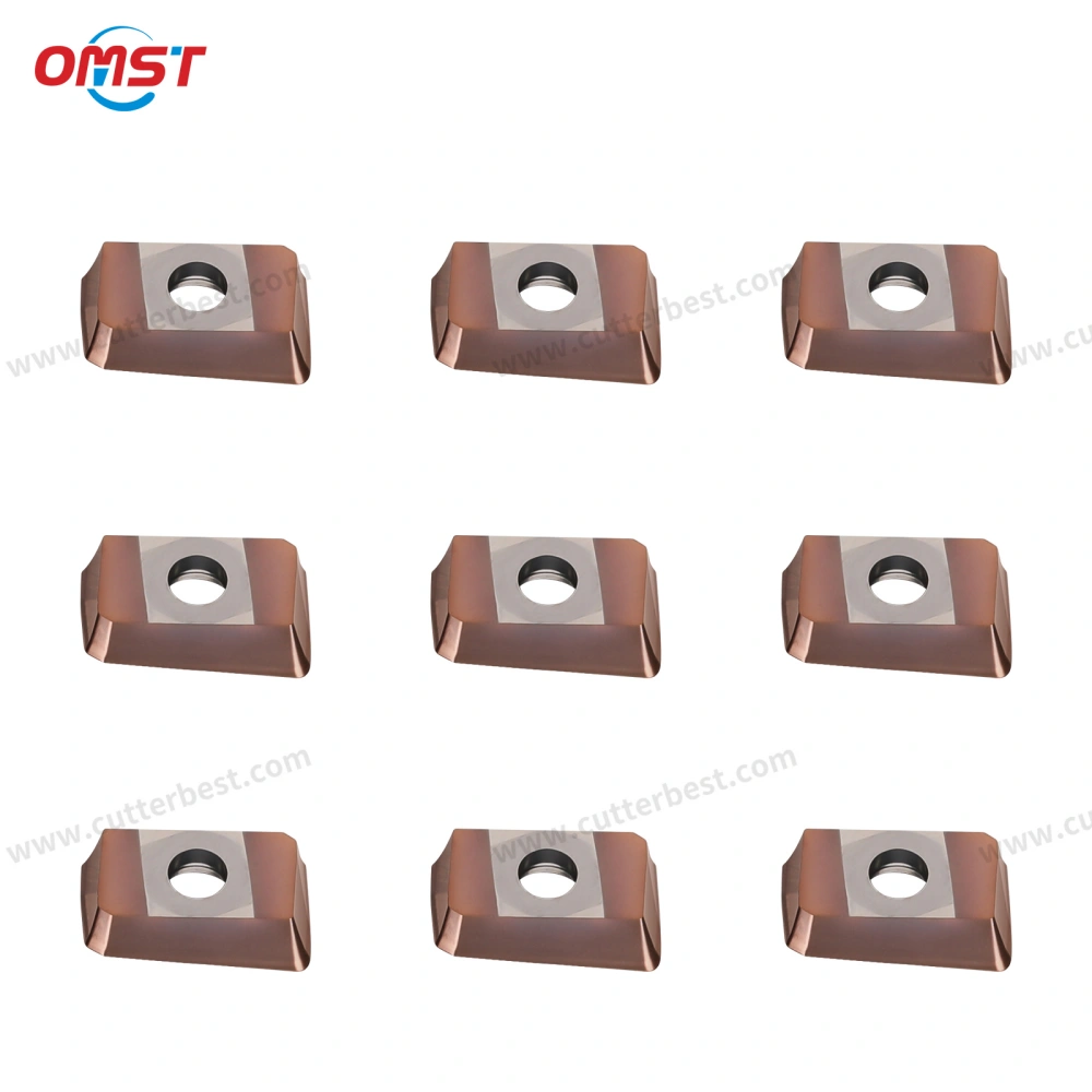
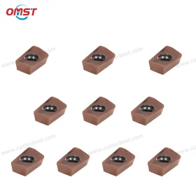
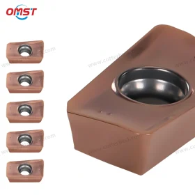
APMT1135 carbide milling inserts are designed for face milling, shoulder milling, step machining, and other general CNC milling operations. The APMT1135PDFR-M2L model combines a tungsten carbide substrate with a coated surface to support stable machining of steel, stainless steel, and cast iron.
Its cutting geometry helps guide chips away from the cutting zone while maintaining consistent contact with the workpiece. Therefore, this insert is suitable for machining workshops, industrial manufacturers, tool distributors, and buyers who need replacement inserts for compatible APMT1135 cutter bodies.
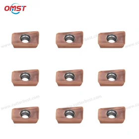
OMST supplies stock products in boxes of 10 pieces. In addition, OEM services can be discussed for distributors and industrial buyers who require private labels, customized packaging, or repeat bulk supply.
APMT1135 Carbide Milling Inserts Overview
What Is APMT1135PDFR-M2L?
APMT1135PDFR-M2L is an indexable carbide insert for compatible CNC milling cutter bodies. CNC operators can use it for flat surface machining, shoulder cutting, step milling, side-wall machining, and general metal removal.
Once the cutting edge reaches its service limit, the insert can be replaced without changing the complete cutter body. As a result, users can control tooling costs and simplify tool maintenance during regular production.
Although many inserts look similar, their dimensions, insert seats, screw positions, and cutting geometries may differ. For this reason, the cutter body model should be checked before an order is confirmed.
Coated Carbide Insert Design
The coated surface helps reduce wear during steel, stainless steel, and cast iron machining. It can also support better heat resistance when suitable cutting parameters are applied.
However, coating alone does not determine insert life. Machine rigidity, workpiece hardness, cutter condition, feed rate, cutting speed, and coolant use also affect the final machining result.
Key Features of APMT1135 Carbide Milling Inserts
Tungsten Carbide Substrate
The insert uses tungsten carbide as its base material. This material provides a practical balance between hardness, toughness, and wear resistance for general CNC milling.
Therefore, the insert can support regular production in mechanical processing, automotive components, mold parts, and other metalworking applications.
Sharp Cutting Geometry
The cutting geometry helps the edge enter the material efficiently. As a result, cutting resistance may be reduced when the insert is installed correctly and the machining parameters match the application.
A stable cutting edge can also support more consistent machining during repeated production cycles.
Smooth Chip Evacuation
The chip-forming surface helps direct chips away from the cutting zone. Smooth chip flow is important during shoulder milling, step milling, and profile machining because accumulated chips may increase heat and affect surface quality.
However, chip evacuation also depends on cutter engagement, coolant conditions, feed rate, and the available chip space.
Wear and Chipping Resistance
The coated surface helps reduce normal abrasive wear. Meanwhile, the carbide substrate provides support against cutting pressure and intermittent contact.
Nevertheless, excessive feed, poor insert seating, cutter vibration, or repeated impact may cause premature edge damage. Therefore, stable installation remains important.
Consistent Surface Quality
A clean insert seat, accurate cutter runout, and suitable cutting parameters can help produce a more consistent machined surface.
For this reason, APMT1135PDFR-M2L can support both general roughing and semi-finishing operations. For applications with strict surface requirements, please provide your material, machining allowance, and finish target before ordering.
Applications of APMT1135 Carbide Milling Inserts
Face Milling
CNC operators can use APMT1135 inserts to machine flat surfaces on CNC milling machines and machining centers.
The final surface condition depends on cutter runout, insert installation, feed per tooth, workpiece clamping, and machine stability. Therefore, all inserts in the cutter body should be installed correctly before machining begins.
Shoulder Milling
With a compatible cutter body, APMT1135PDFR-M2L can machine shoulders, steps, side walls, and near-right-angle features.
Many APMT cutter bodies support square-shoulder milling. However, the final shoulder profile depends on the cutter body design, insert position, and insert seat geometry.
Step and Profile Milling
CNC operators can also use this model for step machining, edge machining, profile milling, and general contour work.
In addition, it can support the regular production of mechanical parts, mold components, automotive components, and industrial hardware.
Roughing and Semi-Finishing
The carbide substrate and coated surface make the insert suitable for general roughing and semi-finishing.
However, very heavy cutting, hardened materials, unstable machining conditions, or severe interrupted cuts may require another insert grade or edge design.
Application and Selection Guide
| Machining Requirement | Recommended Use | Selection Notes |
| Face Milling | Flat surface machining | Check cutter diameter, runout, and feed per tooth |
| Shoulder Milling | Steps, shoulders, and side walls | Confirm cutter geometry and insert seat |
| Step Milling | Multi-level surfaces and edge machining | Use stable clamping and controlled cutter engagement |
| General Roughing | Medium material removal | Select a suitable cutting depth and avoid excessive impact |
| Semi-Finishing | Improved surface consistency | Reduce cutting load and inspect the cutting edge regularly |
| Steel Machining | Carbon steel and alloy steel | Adjust parameters according to material hardness |
| Stainless Steel | General stainless steel milling | Control heat, chip flow, feed rate, and coolant conditions |
| Cast Iron | General cast iron machining | Avoid unstable cutter engagement and excessive impact |
| Aluminum | Not the main application of this coated version | Contact OMST to confirm a more suitable grade |
Workpiece Material Guidance
Steel and Alloy Steel
The coated insert can support general carbon steel and alloy steel machining. For better tool life, users should select the cutting speed, feed rate, and cutting depth according to material hardness and machine rigidity.
In addition, a clean insert seat and stable workpiece fixture can help reduce vibration.
Stainless Steel
CNC operators can use APMT1135PDFR-M2L for general stainless steel machining.
Since stainless steel often generates more heat and may work-harden, stable clamping and controlled cutting parameters are important. Sufficient chip evacuation can also help reduce heat concentration around the cutting edge.
Cast Iron
The coated surface can support cast iron milling under suitable machining conditions.
However, users should avoid excessive impact and confirm that the cutter body provides stable insert support. The insert seat should also be inspected before installation.
Aluminum and Non-Ferrous Materials
OMST mainly recommends this coated version for steel, stainless steel, and cast iron.
For aluminum, copper, brass, or other non-ferrous materials, please contact OMST to confirm whether another carbide grade, coating, or cutting-edge design would provide better performance.
Cutting Performance Considerations
Machine and Fixture Rigidity
A rigid machine and stable fixture help reduce vibration. As a result, the cutting edge can maintain more consistent contact with the workpiece.
If vibration occurs, users should check the tool overhang, cutter body, fixture, cutting load, and spindle condition.
Cutter Body Condition
The insert seat, screw, and cutter body should remain clean and free from damage.
Poor seating can affect cutter runout, cutting stability, surface quality, and insert life. Therefore, chips and dirt should be removed before a new insert is installed.
Cutting Parameters
Cutting speed, feed rate, axial depth, and radial engagement should match the workpiece material and cutter body.
Buyers should not copy cutting parameters from another machine without checking the actual machining conditions. Instead, initial parameters should be tested and adjusted gradually.
Coolant and Chip Control
Coolant selection depends on the material and machining process. In some applications, compressed air or dry cutting may be used.
However, stainless steel machining often requires better heat and chip control. Consistent coolant delivery may also help prevent repeated thermal shock.
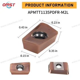
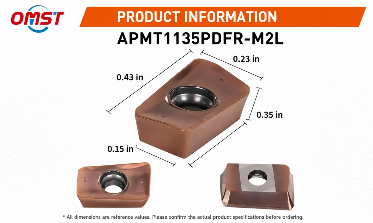
Please refer to the APMT1135PDFR-M2L dimension image for the product size and structural reference.
Because different manufacturers may use different suffixes, chipbreaker designs, or small dimensional variations, the image should be treated as a reference. Before bulk orders, please confirm the cutter body model, insert seat, and required dimensions.
What Is the Corner Radius of an APMT1135 Insert?
The corner radius of an APMT1135 insert may vary according to the complete model designation, manufacturer, chipbreaker design, and cutting-edge geometry.
Therefore, buyers should not select an insert by the APMT1135 size code alone. Different suffixes may represent different cutting structures or application requirements.
Before ordering, please provide:
Current insert marking
Required corner radius
Cutter body model
Insert seat photo
Product drawing, if available
OMST will use this information to help confirm the correct insert dimensions and cutter body compatibility.
Compatible Cutter Bodies
APMT1135PDFR-M2L inserts are intended for cutter bodies designed for APMT1135-size inserts. These may include compatible indexable end mills, shoulder milling cutters, face milling cutters, and other APMT-style cutter bodies.
However, similar-looking inserts are not always interchangeable. Different cutter brands may use different insert seats, screw positions, clearance angles, or chipbreaker requirements.
Therefore, please send the following information before ordering:
Cutter body model
Existing insert marking
Insert seat photo
Product drawing, if available
Required order quantity
OMST will help check compatibility before production or shipment.
APMT1135 vs APMT1604 Inserts
APMT1135 and APMT1604 belong to the same general APMT insert family, but they have different sizes and may fit different cutter bodies.
APMT1604 is larger and may support different cutter diameters or cutting loads. However, buyers should select the insert according to the cutter body model and insert seat rather than choosing only by insert size.
For the larger model, view our APMT1604 carbide milling inserts.
APMT1135 vs APKT1135 Inserts
APMT1135 and APKT1135 are both indexable milling inserts, but they belong to different insert series.
Their insert geometry, cutting-edge design, seat structure, and compatible cutter bodies may differ. Therefore, they should not be treated as interchangeable models without technical confirmation.
For another 1135-size insert option, view our APKT1135 carbide milling inserts.
OEM and Supply Support
OMST supports trial orders, regular stock orders, and bulk purchasing for industrial users, resellers, and cutting tool distributors.
Available OEM options may include:
Laser marking
Private label packaging
Customized product labels
Edge preparation
Coating selection for qualified bulk orders
The final MOQ and delivery time depend on quantity, coating, packaging, and technical requirements.
Why Choose OMST?
Milling Insert Supply Experience
OMST supplies milling inserts, turning inserts, CNC cutting tools, and customized tooling solutions for industrial machining applications.
Our team can review the workpiece material, cutter body model, machining method, and purchase quantity before quotation.
Technical Selection Support
Insert selection should consider more than the basic size code.
Therefore, OMST can help buyers check the current insert marking, application, cutter body, material, and required edge geometry before the order is placed.
Trial Orders and Bulk Supply
Stock products are packed in boxes of 10 pieces, and the standard MOQ for available items is one box.
In addition, stable repeat supply and OEM packaging can be discussed for distributors and regular industrial buyers.
Related Milling Tool Options
For additional CNC milling solutions, view our CNC milling cutters.
You can also review our carbide milling cutter product range.
For other milling insert models, compare this product with our APMT1604 carbide milling inserts.
Another available 1135-size option is our APKT1135 carbide milling inserts.
Request a Quote for APMT1135 Carbide Milling Inserts
Please send us your workpiece material, cutter body model, current insert marking, required corner radius, machining application, order quantity, and packaging requirements.
OMST will help confirm whether APMT1135PDFR-M2L carbide milling inserts match your cutter body and machining conditions. After the technical details are confirmed, we will provide a quotation based on your order requirements.