 Fresas de precisión,Herramientas de corte para el mecanizado CNC de todos los materiales

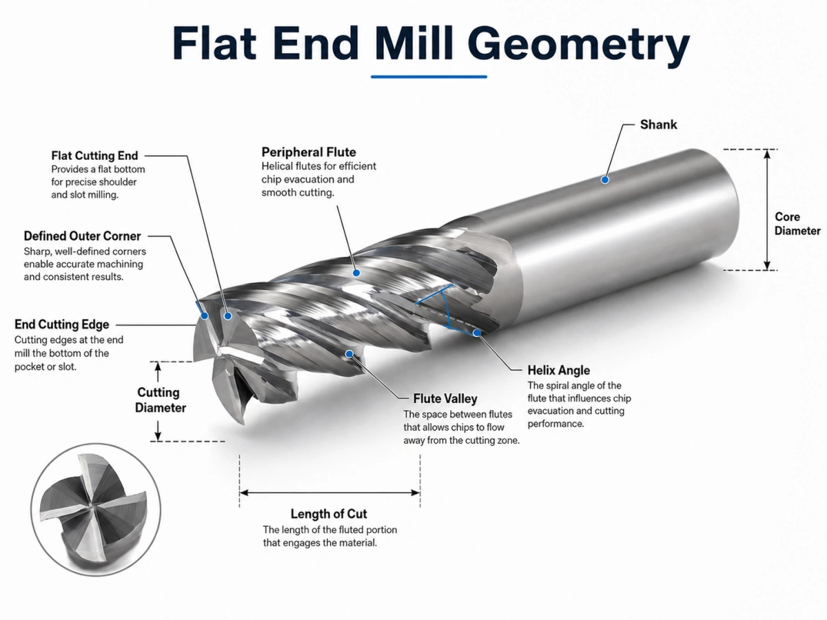
A flat end mill is a rotating milling cutter with a flat cutting profile and defined outer corners. Its end cutting edges remove material near the tool bottom, while the peripheral flutes cut along the side of the workpiece. This geometry helps create flat surfaces, paredes rectas, and clear bottom-to-wall transitions.
Sin embargo, the end profile alone does not determine machining performance. recuento de flautas, diámetro del núcleo, ángulo de hélice, longitud de corte, preparación de bordes, revestimiento, and tool overhang all affect how the cutter behaves under load.
Two tools with the same cutting diameter can therefore produce very different results. A low-flute-count design may evacuate aluminum chips efficiently, while a higher-flute-count cutter may provide the rigidity needed for steel machining or finishing.
For available tool materials, dimensiones, flauta cuenta, revestimientos, y opciones personalizadas, revisa nuestro molino de extremo plano página del producto.
Geometría del molino de extremo plano: The Features That Matter
A flat end mill is more than a cutter with a flat bottom. Its performance depends on the relationship between the cutting corners, flute valleys, centro, ángulo de hélice, end cutting edges, and peripheral flutes.
Flat Cutting End and Outer Corners
The cutting end has a generally flat profile. Its outer corners connect the end cutting edges with the peripheral cutting edges.
A sharp corner creates a clear transition between the bottom and side wall. Sin embargo, it also concentrates cutting stress. Corner chipping becomes more likely when the setup has excessive runout, largo voladizo, corte interrumpido, or aggressive engagement.
When the part drawing allows a corner radius, a bull nose design can strengthen the cutting corner. When the component requires a sharper internal transition, a flat end profile remains the more suitable option.
End and Peripheral Cutting Edges
The end cutting edges remove material near the tool bottom. Their detailed geometry also affects how the cutter enters the workpiece.
Do not assume that every flat end mill can plunge directly into solid material. Some designs support controlled plunging, rampa, o entrada helicoidal. Other tools may require side entry or an existing opening.
Peripheral cutting edges run along the outside diameter. They influence side-wall accuracy, radial cutting action, formación de virutas, fuerzas de corte, y acabado superficial.
Flute Valley and Core Diameter
The flute valley provides space for chip flow. Mientras tanto, the core is the solid material that supports the cutting edges.
This creates a practical trade-off:
- Larger flute valleys improve chip evacuation.
- A larger core increases tool rigidity.
- More cutting edges may improve productivity or surface quality.
- Too many flutes can cause chip packing in deep slots.
A lower flute count is often selected when chip volume is high. A higher flute count is more common when radial engagement is lower and rigidity or finishing performance matters more.
Ángulo de hélice
The helix angle controls how gradually the cutting edge enters the material and how cutting forces move through the cutter.
Typical starting points include:
- Around 35°–40° for general machining and stronger cutting edges
- Around 45° for smoother cutting and finishing
- Higher helix angles for improved chip flow, with greater axial force
- Lower helix angles for stronger edges and lower lifting force
These values are not fixed rules. Diámetro de herramienta, material de la pieza de trabajo, recuento de flauta, compromiso, and machine rigidity still determine the final geometry.
Cutting Length and Tool Overhang
Long cutting edges improve reach, but they reduce rigidity. Como resultado, the cutter becomes more sensitive to deflection, sin, y vibración.
Use the shortest practical flute length and tool overhang whenever possible. A rigid holder, low runout, and a strong shank also improve stability.
A short-flute, long-neck design can often reach a deep feature with better rigidity than a fully fluted long cutter.
How Does a Flat End Mill Cut?
The spindle rotates the cutter while the CNC machine controls its movement relative to the workpiece. Each cutting edge enters the material, forms a chip, and leaves the cutting zone.
The end edges act near the tool bottom. Mientras tanto, the peripheral flutes cut the side of the feature. The actual load distribution depends on axial depth, compromiso radial, método de entrada, y trayectoria.
Chip Formation and Evacuation
Each cutting edge shears a chip from the workpiece. The flute must then carry the chip away before the next edge reaches the same area.
Poor chip evacuation may cause:
- Recorte de viruta
- calor excesivo
- Borde construido
- Daños de vanguardia
- Mal acabado superficial
Chip control becomes especially important during deep pocket machining, ranurado de ancho completo, mecanizado de aluminio, and other high-volume cutting operations.
Air blast, refrigerante, or another suitable chip-removal method should match the material and machining process. The main objective is simple: chips must leave the cutting zone quickly and consistently.
Practical Geometry Choices by Material
The following tables provide practical starting points. Final selection still depends on the material grade, dureza, diámetro de la herramienta, condición de la máquina, método de refrigerante, y trayectoria.
Typical Geometry by Workpiece Material
| Pieza de trabajo | Typical Geometry | Main Risk |
| Aluminum and non-ferrous alloys | 2–3 flautas, grandes valles de flauta, sharp or polished edges | Chip welding and built-up edge |
| acero general | 4 or more flutes with a stronger core | Calor, tener puesto, and deflection |
| Acero inoxidable | Rigid tool, stable edge, controlled engagement | Heat and work hardening |
| Hierro fundido | Wear-resistant substrate and reinforced edge | Abrasive wear |
| Acero endurecido | Strong core, voladizo corto, reinforced edge | Chipping and rapid wear |
Typical Coating Direction
| Pieza de trabajo | Coating Direction | Enfoque de selección |
| Aluminum and non-ferrous alloys | Sin recubrimiento, contenido descargable, TiB2, or another suitable option | Baja fricción y adherencia reducida. |
| acero general | TiAlN, Altin, o revestimiento para aplicaciones específicas | Heat and wear resistance |
| Acero inoxidable | Heat-resistant coating selected by material grade | Stable cutting and heat control |
| Hierro fundido | Wear-resistant coating | Abrasion resistance |
| Acero endurecido | High-temperature coating selected by actual HRC | Edge strength and heat resistance |
Para aluminio, espacio de chip, sharp edges, and low material adhesion are usually the main priorities. Dos- or three-flute designs often provide more room for chip evacuation.
For general steel, rigidity and heat resistance usually become more important. Four or more flutes may work well when chip load and radial engagement remain under control.
For hardened steel, always provide the actual hardness. HRC 45, HRC 55, y CDH 65 require different tool materials, preparaciones de bordes, revestimientos, y parámetros de corte.
Coating and Edge Preparation
Uncoated or polished tools often suit aluminum, cobre, y otros materiales no ferrosos. Their sharp, low-friction surfaces help reduce built-up edge.
TiAlN and AlTiN coatings are widely used for steel, acero inoxidable, acero para herramientas, and other heat-intensive applications. Sin embargo, coating selection must still match the exact workpiece grade and machining conditions.
DLC and similar low-friction coatings are often considered for aluminum and other non-ferrous materials because they can reduce material adhesion.
Edge preparation matters as much as coating. A very sharp edge lowers cutting force but may chip during hard or interrupted cutting. A light hone strengthens the edge, although it also increases cutting force.
Flat End Mill Troubleshooting Guide
| Problema | Likely Cause | Practical Correction |
| Charla | Largo voladizo, weak holding, or high engagement | Shorten overhang and reduce engagement |
| Tapered wall | Tool deflection or excessive cutting load | Use a shorter tool or add a finishing pass |
| Embalaje de chips | Too many flutes or poor chip removal | Use fewer flutes and improve chip evacuation |
| Borde construido | Unsuitable edge, revestimiento, or chip load | Use a sharper edge and suitable lubrication |
| astillado de esquina | Sin, impact, or interrupted cutting | Reduce entry shock and check runout |
| Poor finish | Charla, recutting, or deflection | Improve rigidity and remove chips effectively |
How to Reduce Chatter and Deflection
Start with the mechanical setup:
- Reduce tool overhang.
- Use the shortest practical cutting length.
- Improve holder and workpiece rigidity.
- Reduce radial or axial engagement.
- Avoid sudden full engagement in internal corners.
- Dejar un margen de acabado controlado.
Do not reduce feed to an extremely low value without checking chip load. Feeding too slowly can cause the cutting edge to rub instead of cut. This increases heat and may worsen surface finish.
How to Improve Chip Evacuation
For deep slots and high chip volume:
- Choose fewer flutes or larger flute valleys.
- Direct air or coolant into the cutting zone.
- Prevent chips from being cut again.
- Reduce axial depth when chips cannot escape.
- Consider chipbreaker geometry for long chips.
Flat End Mill vs Square End Mill
In many solid end mill catalogs, “flat end mill” and “square end mill” describe the same general geometry: a flat cutting end with defined outer corners.
The terms emphasize different details:
- “Flat” describes the bottom profile.
- “Square” describes the corner where the end and peripheral cutting edges meet.
Buyers should still confirm the drawing. Some suppliers distinguish between a sharp corner, a small protective chamfer, and a small corner radius.
A square end mill is also different from a square shoulder milling cutter. A square shoulder cutter describes a tool or milling system designed to produce a 90° shoulder. It may use indexable inserts and may not resemble a solid flat end mill.
Flat End Mill vs Bull Nose and Ball Nose Geometry
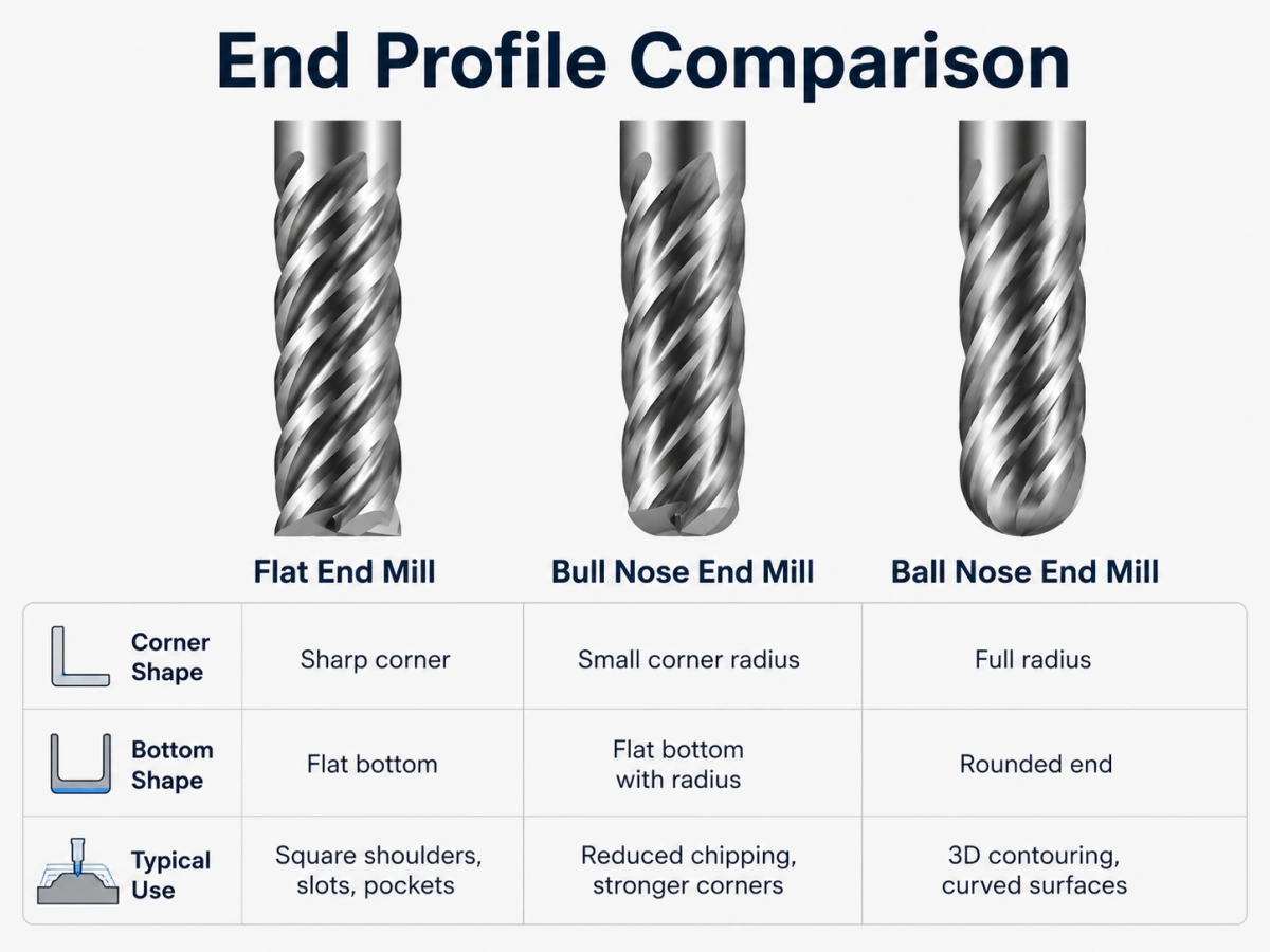
Departamento, Nariz de toro, and Ball Nose Comparison
| Tool Profile | Geometría final | Main Effect |
| Fresa de extremo plano | Flat end with defined corners | Produces flat bottoms and sharper transitions |
| Molino de punta de toro | Flat center with corner radii | Strengthens corners and reduces chipping |
| Molino de extremo de punta esférica | Fully rounded end | Supports curved and 3D surface machining |
A bull nose end mill strengthens the cutting corner, while a flat profile preserves a sharper internal transition. Para una comparación más detallada, leer fresa de punta toro versus fresa plana.
For fully rounded cutting-end geometries, revisa nuestro Fresas de punta esférica.
What Information Should You Send to a Tool Supplier?
A professional recommendation requires more than the tool diameter.
Send the following information:
- Workpiece material and exact grade
- Dureza del material, including HRC when applicable
- Diámetro de corte
- longitud de la flauta
- Longitud total
- Diámetro del mango
- Required reach or neck length
- recuento de flautas
- Machining operation and entry method
- Coolant or dry-cutting condition
- Required tolerance and surface finish
- Cantidad de pedido
- Dibujo de herramienta o dibujo de pieza.
This information helps the supplier evaluate the tool material, geometría de la flauta, ángulo de hélice, preparación de bordes, revestimiento, and rigidity.
For non-standard dimensions or application-specific tools, revisa nuestro fresas personalizadas servicio.
Preguntas frecuentes
What is another name for a flat end mill?
Many suppliers also use the term square end mill. Some catalogs use flat bottom end mill, although the drawing should confirm the actual corner geometry.
Are all flat end mills made of solid carbide?
No. Tool material and construction can be selected according to the workpiece, máquina, production volume, condiciones de corte, y requisitos del cliente.
Can flat end mills have different flute counts?
Sí. Dos, tres, cuatro, six, and custom flute counts are possible. The correct choice depends on chip volume, rigidez, compromiso, material, y requisitos de acabado superficial.
Is every flat end mill suitable for direct plunging?
No. Direct plunging depends on the center and end-cutting geometry. Confirm whether the tool supports plunging, rampa, entrada helicoidal, entrada lateral, or machining from an existing opening.
Conclusión
A flat end mill is defined by its flat cutting profile and defined outer corners. Its performance depends on the relationship between flute valley, fuerza central, ángulo de hélice, longitud de corte, preparación de bordes, revestimiento, y saliente de la herramienta.
The machining result also provides useful clues. Chatter points toward instability or excessive engagement. Tapered walls suggest deflection. Chip packing indicates poor evacuation. Corner damage may show that the edge geometry or cutting load does not match the job.
Understanding these signals helps engineers select a more suitable cutter. También brinda a los equipos de compras la información necesaria para solicitar una cotización precisa..
Discuta su requisito de fresa de extremo plano
Revise nuestros estándares y personalizados. molino de extremo plano opciones para diferentes materiales de herramientas, tamaños, flauta cuenta, ángulos de hélice, revestimientos, y condiciones de mecanizado.
Por favor envíe el material de su pieza de trabajo., dureza, dimensiones de la herramienta, operación de mecanizado, cantidad, y dibujo si esta disponible.
Email: sales@cutterbest.com