 Frese di precisione,Utensili da taglio per la lavorazione CNC di ogni materiale

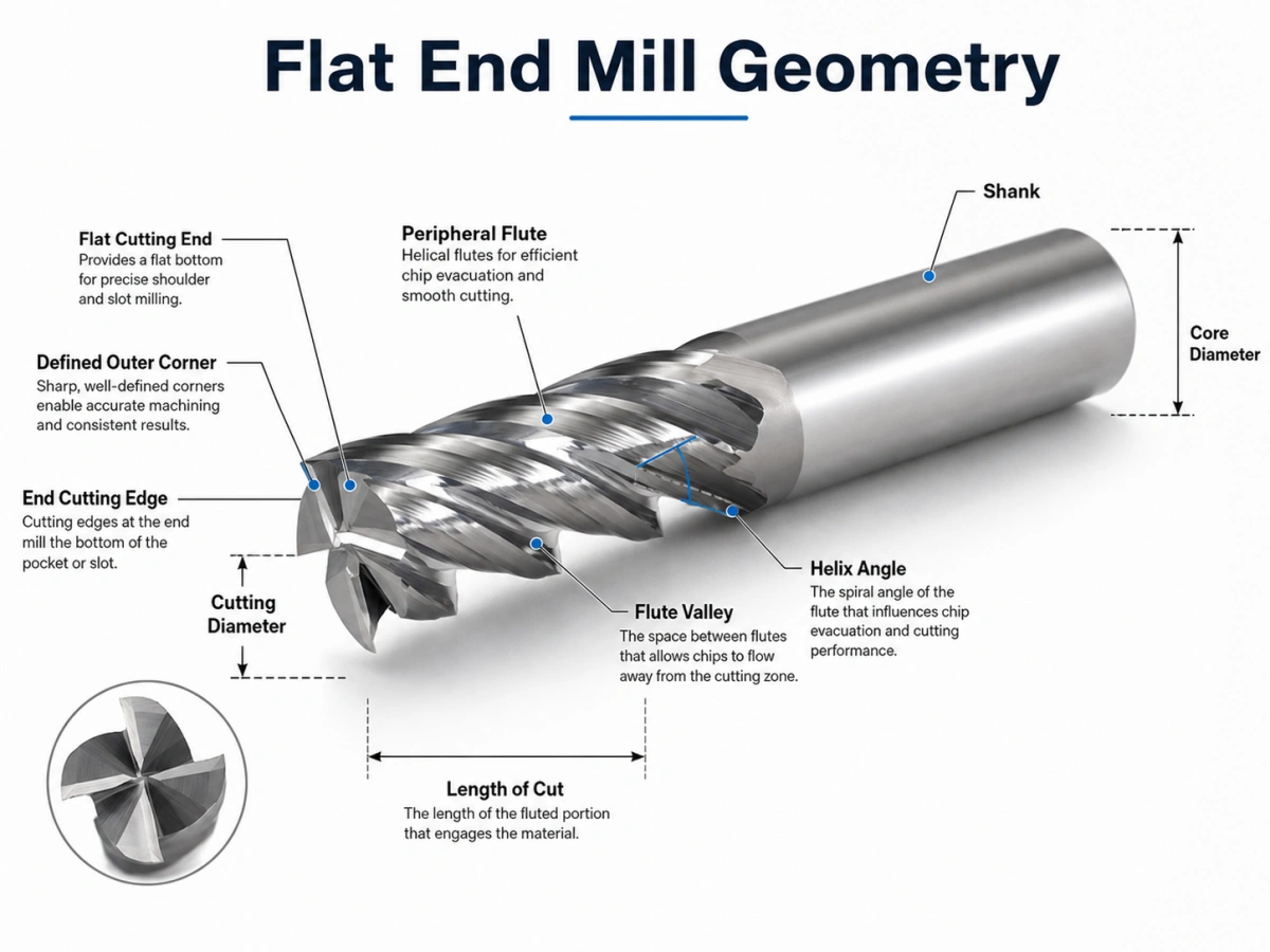
Una fresa a candela piatta è una fresa rotante con un profilo di taglio piatto e angoli esterni definiti. I suoi taglienti terminali rimuovono il materiale vicino al fondo dell'utensile, mentre le scanalature periferiche tagliano lungo il lato del pezzo. Questa geometria aiuta a creare superfici piane, pareti diritte, e chiare transizioni dal fondo alla parete.
Tuttavia, il solo profilo finale non determina le prestazioni di lavorazione. Conteggio del flauto, diametro del nucleo, angolo dell'elica, lunghezza di taglio, preparazione dei bordi, rivestimento, e la sporgenza dell'utensile influiscono tutti sul comportamento della fresa sotto carico.
Due utensili con lo stesso diametro di taglio possono quindi produrre risultati molto diversi. Un design a basso numero di scanalature può evacuare i trucioli di alluminio in modo efficiente, mentre una fresa con un numero maggiore di scanalature può fornire la rigidità necessaria per la lavorazione o la finitura dell'acciaio.
Per i materiali degli utensili disponibili, dimensioni, conta il flauto, rivestimenti, e opzioni personalizzate, rivedi il nostro fresa a punta piatta pagina del prodotto.
Geometria della fresa a estremità piatta: Le caratteristiche che contano
Una fresa a punta piatta è più di una fresa con fondo piatto. Le sue prestazioni dipendono dal rapporto tra gli angoli taglienti, valli del flauto, nucleo, angolo dell'elica, taglienti finali, e flauti periferici.
Estremità di taglio piatta e angoli esterni
L'estremità tagliente ha un profilo generalmente piatto. I suoi angoli esterni collegano i taglienti terminali con i taglienti periferici.
Un angolo acuto crea una chiara transizione tra il fondo e la parete laterale. Tuttavia, concentra anche lo stress da taglio. La scheggiatura degli angoli diventa più probabile quando l'impostazione presenta un runout eccessivo, lungo sbalzo, taglio interrotto, o impegno aggressivo.
Quando il disegno della parte consente un raggio d'angolo, un design a toro può rafforzare l'angolo di taglio. Quando il componente richiede una transizione interna più netta, un profilo con estremità piatta rimane l'opzione più adatta.
Taglienti terminali e periferici
I taglienti terminali rimuovono il materiale vicino al fondo dell'utensile. La loro geometria dettagliata influisce anche sul modo in cui la fresa entra nel pezzo.
Non dare per scontato che ogni fresa a candela possa immergersi direttamente nel materiale solido. Alcuni progetti supportano l'immersione controllata, rampante, o ingresso elicoidale. Altri strumenti potrebbero richiedere l'ingresso laterale o un'apertura esistente.
I taglienti periferici corrono lungo il diametro esterno. Influenzano la precisione della parete laterale, azione di taglio radiale, formazione di trucioli, forze di taglio, e finitura superficiale.
Valle del flauto e diametro del nucleo
La valle del flauto offre spazio per il deflusso dei trucioli. Nel frattempo, il nucleo è il materiale solido che supporta i taglienti.
Ciò crea un compromesso pratico:
- Gli avvallamenti più grandi migliorano l'evacuazione dei trucioli.
- Un nucleo più grande aumenta la rigidità dell'utensile.
- Un numero maggiore di taglienti può migliorare la produttività o la qualità della superficie.
- Troppe scanalature possono causare l'accumulo di trucioli nelle scanalature profonde.
Spesso viene selezionato un numero di scanalature inferiore quando il volume del truciolo è elevato. Un numero maggiore di scanalature è più comune quando l'impegno radiale è inferiore e la rigidità o le prestazioni di finitura sono più importanti.
Angolo dell'elica
L'angolo dell'elica controlla la gradualità con cui il tagliente entra nel materiale e il modo in cui le forze di taglio si muovono attraverso la fresa.
I punti di partenza tipici includono:
- Circa 35°–40° per lavorazioni generali e taglienti più robusti
- Circa 45° per un taglio e una finitura più fluidi
- Angoli dell'elica più elevati per un migliore deflusso dei trucioli, con maggiore forza assiale
- Angoli dell'elica più bassi per bordi più forti e forza di sollevamento inferiore
Questi valori non sono regole fisse. Diametro dell'utensile, materiale del pezzo, conteggio dei flauti, fidanzamento, e la rigidità della macchina determinano ancora la geometria finale.
Lunghezza di taglio e sporgenza dell'utensile
I taglienti lunghi migliorano la portata, ma riducono la rigidità. Di conseguenza, la taglierina diventa più sensibile alla deflessione, esaurire, e vibrazioni.
Quando possibile, utilizzare la lunghezza della scanalatura e la sporgenza dell'utensile più corte. Un supporto rigido, basso runout, e un gambo forte migliora anche la stabilità.
Un flauto corto, il design a collo lungo può spesso raggiungere un elemento profondo con una rigidità migliore rispetto a una fresa lunga completamente scanalata.
Come taglia una fresa a punta piatta?
Il mandrino fa ruotare la fresa mentre la macchina CNC ne controlla il movimento rispetto al pezzo. Ogni tagliente entra nel materiale, forma un chip, e lascia la zona di taglio.
I bordi terminali agiscono vicino al fondo dell'utensile. Nel frattempo, le scanalature periferiche tagliano il lato dell'elemento. La distribuzione effettiva del carico dipende dalla profondità assiale, impegno radiale, metodo di immissione, e percorso utensile.
Formazione ed evacuazione del truciolo
Ciascun tagliente elimina un truciolo dal pezzo. La scanalatura deve quindi portare via il truciolo prima che il bordo successivo raggiunga la stessa area.
Potrebbe verificarsi una scarsa evacuazione dei trucioli:
- Ritaglio del truciolo
- Calore eccessivo
- Bordo costruito
- Danni all'avanguardia
- Finitura superficiale scadente
Il controllo del truciolo diventa particolarmente importante durante la lavorazione di tasche profonde, scanalatura a tutta larghezza, lavorazione dell'alluminio, e altre operazioni di taglio ad alto volume.
Esplosione d'aria, refrigerante, oppure un altro metodo di rimozione dei trucioli adatto deve corrispondere al materiale e al processo di lavorazione. L'obiettivo principale è semplice: i trucioli devono lasciare la zona di taglio in modo rapido e uniforme.
Scelte pratiche di geometria in base al materiale
Le tabelle seguenti forniscono punti di partenza pratici. La selezione finale dipende ancora dalla qualità del materiale, durezza, diametro dell'utensile, condizione della macchina, metodo del refrigerante, e percorso utensile.
Geometria tipica per materiale del pezzo
| Pezzo | Geometria tipica | Rischio principale |
| Alluminio e leghe non ferrose | 2–3 flauti, grandi valli del flauto, bordi affilati o lucidati | Saldatura truciolo e tagliente di riporto |
| Acciaio generale | 4 o più flauti con un nucleo più forte | Calore, Indossare, e deflessione |
| Acciaio inossidabile | Strumento rigido, bordo stabile, impegno controllato | Calore e incrudimento |
| Ghisa | Substrato resistente all'usura e bordo rinforzato | Usura abrasiva |
| Acciaio temprato | Nucleo forte, breve sbalzo, bordo rinforzato | Scheggiature e rapida usura |
Direzione tipica del rivestimento
| Pezzo | Direzione del rivestimento | Focus della selezione |
| Alluminio e leghe non ferrose | Non rivestito, DLC, TiB2, o un'altra opzione adatta | Low friction and reduced adhesion |
| Acciaio generale | TiAlN, Altin, o rivestimento specifico per l'applicazione | Resistenza al calore e all'usura |
| Acciaio inossidabile | Rivestimento resistente al calore selezionato in base alla qualità del materiale | Taglio stabile e controllo del calore |
| Ghisa | Rivestimento resistente all'usura | Resistenza all'abrasione |
| Acciaio temprato | Rivestimento ad alta temperatura selezionato dall'HRC effettivo | Robustezza dei bordi e resistenza al calore |
Per alluminio, spazio per i chip, spigoli vivi, e la bassa adesione del materiale sono solitamente le priorità principali. Due- o i design a tre eliche spesso offrono più spazio per l’evacuazione dei trucioli.
Per acciaio generale, la rigidità e la resistenza al calore di solito diventano più importanti. Quattro o più scanalature possono funzionare bene quando il carico del truciolo e l'impegno radiale rimangono sotto controllo.
Per acciaio temprato, fornire sempre la durezza effettiva. HRC 45, HRC 55, e HRC 65 richiedono materiali diversi per gli utensili, preparazioni dei bordi, rivestimenti, e parametri di taglio.
Rivestimento e preparazione dei bordi
Gli utensili non rivestiti o lucidati spesso sono adatti all'alluminio, rame, e altri materiali non ferrosi. Il loro acuto, le superfici a basso attrito aiutano a ridurre il tagliente di riporto.
I rivestimenti TiAlN e AlTiN sono ampiamente utilizzati per l'acciaio, acciaio inossidabile, acciaio per utensili, e altre applicazioni ad alta intensità di calore. Tuttavia, la selezione del rivestimento deve comunque corrispondere all'esatto grado del pezzo e alle condizioni di lavorazione.
DLC e rivestimenti simili a basso attrito sono spesso presi in considerazione per l'alluminio e altri materiali non ferrosi perché possono ridurre l'adesione del materiale.
La preparazione dei bordi è importante tanto quanto il rivestimento. Un tagliente molto affilato riduce la forza di taglio ma può scheggiarsi durante il taglio duro o interrotto. Una leggera affilatura rinforza il filo, sebbene aumenti anche la forza di taglio.
Guida alla risoluzione dei problemi delle frese a punta piatta
| Problema | Probabile causa | Correzione pratica |
| Chiacchiere | Sbalzo lungo, tenuta debole, o alto coinvolgimento | Accorciare lo sbalzo e ridurre l'impegno |
| Parete rastremata | Deflessione dell'utensile o carico di taglio eccessivo | Utilizzare uno strumento più corto o aggiungere una passata di finitura |
| Imballaggio dei trucioli | Troppe scanalature o scarsa rimozione dei trucioli | Utilizzare meno eliche e migliorare l'evacuazione dei trucioli |
| Bordo costruito | Bordo non adatto, rivestimento, o carico di trucioli | Utilizzare un tagliente più affilato e una lubrificazione adeguata |
| Scheggiatura degli angoli | Esaurire, impatto, o taglio interrotto | Ridurre lo shock in entrata e controllare il runout |
| Finitura scadente | Chiacchiere, ritaglio, o deflessione | Migliora la rigidità e rimuove i trucioli in modo efficace |
Come ridurre le chiacchiere e la deflessione
Inizia con la configurazione meccanica:
- Ridurre la sporgenza dell'utensile.
- Utilizzare la lunghezza di taglio pratica più corta.
- Migliorare la rigidità del supporto e del pezzo.
- Ridurre l'impegno radiale o assiale.
- Evitare il pieno impegno improvviso negli angoli interni.
- Lasciare un margine di rifinitura controllato.
Non ridurre l'avanzamento a un valore estremamente basso senza controllare il carico del truciolo. Un'alimentazione troppo lenta può causare lo sfregamento del tagliente anziché il taglio. Ciò aumenta il calore e può peggiorare la finitura superficiale.
Come migliorare l'evacuazione dei trucioli
Per scanalature profonde ed elevato volume di trucioli:
- Scegli meno flauti o valli più grandi.
- Dirigere aria o refrigerante nella zona di taglio.
- Evitare che i trucioli vengano nuovamente tagliati.
- Ridurre la profondità assiale quando i trucioli non possono fuoriuscire.
- Considerare la geometria del rompitruciolo per trucioli lunghi.
Fresa a punta piatta vs fresa a punta quadrata
In molti cataloghi di frese integrali, “fresa a testa piatta” e “fresa a testa quadra” descrivono la stessa geometria generale: un'estremità tagliente piatta con angoli esterni definiti.
I termini enfatizzano dettagli diversi:
- "Piatto" descrive il profilo inferiore.
- "Quadrato" descrive l'angolo in cui si incontrano i taglienti finali e periferici.
Gli acquirenti dovrebbero comunque confermare il disegno. Alcuni fornitori distinguono tra uno spigolo vivo, un piccolo smusso protettivo, e un piccolo raggio d'angolo.
Anche una fresa a candela quadrata è diversa da una fresa per spallamenti quadrati. Una fresa per spallamenti quadrati descrive un utensile o un sistema di fresatura progettato per produrre uno spallamento a 90°. Può utilizzare inserti indicizzabili e potrebbe non assomigliare a una fresa piana solida.
Fresa a testa piatta rispetto alla geometria a testa sferica e a punta sferica
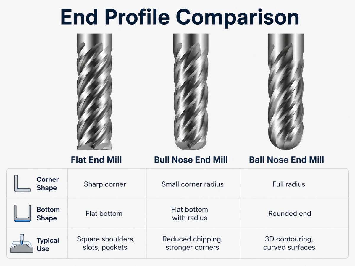
Piatto, Naso di toro, e confronto del naso sferico
| Profilo dello strumento | Fine della geometria | Effetto principale |
| Fresa a testa piatta | Estremità piatta con angoli definiti | Produce fondi piatti e transizioni più nette |
| Fresa a punta di toro | Centro piatto con raggi d'angolo | Rafforza gli angoli e riduce le scheggiature |
| Fresa a candela a testa sferica | Estremità completamente arrotondata | Supporta la lavorazione di superfici curve e 3D |
Una fresa a testa tonda rafforza l'angolo di taglio, mentre un profilo piatto preserva una transizione interna più netta. Per un confronto più dettagliato, Leggere fresa a punta toro vs fresa piana.
Per geometrie dei taglienti completamente arrotondati, rivedi il nostro Frese a candela a testa sferica.
Quali informazioni dovresti inviare a un fornitore di strumenti?
Una raccomandazione professionale richiede più del diametro dell'utensile.
Invia le seguenti informazioni:
- Materiale del pezzo e qualità esatta
- Durezza del materiale, incluso HRC quando applicabile
- Diametro di taglio
- Lunghezza del flauto
- Lunghezza
- Diametro del gambo
- Portata o lunghezza del collo richiesta
- Conteggio del flauto
- Operazione di lavorazione e metodo di immissione
- Condizioni di refrigerante o taglio a secco
- Tolleranza richiesta e finitura superficiale
- Quantità dell'ordine
- Disegno dello strumento o disegno della parte
Queste informazioni aiutano il fornitore a valutare il materiale dell'utensile, geometria del flauto, angolo dell'elica, preparazione dei bordi, rivestimento, e rigidità.
Per dimensioni non standard o utensili specifici per l'applicazione, rivedi il nostro frese personalizzate servizio.
Domande frequenti
Qual è un altro nome per una fresa a testa piatta?
Molti fornitori utilizzano anche il termine fresa a candela quadra. Alcuni cataloghi utilizzano frese a fondo piatto, sebbene il disegno dovrebbe confermare la geometria effettiva dell'angolo.
Tutte le frese a candela sono realizzate in metallo duro integrale?
NO. Il materiale e la costruzione dell'utensile possono essere selezionati in base al pezzo, macchina, volume di produzione, condizioni di taglio, e requisiti del cliente.
Le frese a testa piatta possono avere un numero di scanalature diverso?
Sì. Due, tre, quattro, sei, e sono possibili conteggi di flauto personalizzati. La scelta corretta dipende dal volume del chip, rigidità, fidanzamento, materiale, e requisiti di finitura superficiale.
Tutte le frese a candela sono adatte per la lavorazione a tuffo diretto??
NO. La penetrazione diretta dipende dalla geometria del centro e del tagliente. Confermare se l'utensile supporta l'immersione, rampante, entrata elicoidale, ingresso laterale, o lavorazione da un'apertura esistente.
Conclusione
Una fresa a candela piatta è definita dal profilo di taglio piatto e dagli angoli esterni definiti. Le sue prestazioni dipendono dal rapporto tra la valle del flauto, forza fondamentale, angolo dell'elica, lunghezza di taglio, preparazione dei bordi, rivestimento, e sporgenza dell'utensile.
Il risultato della lavorazione fornisce anche indizi utili. Le chiacchiere indicano instabilità o coinvolgimento eccessivo. Le pareti affusolate suggeriscono una deflessione. L'impaccamento dei trucioli indica una scarsa evacuazione. I danni agli angoli possono indicare che la geometria del tagliente o il carico di taglio non corrispondono al lavoro.
Comprendere questi segnali aiuta gli ingegneri a selezionare una fresa più adatta. Fornisce inoltre ai team di acquisto le informazioni necessarie per richiedere un preventivo accurato.
Discuti i tuoi requisiti di fresa a punta piana
Rivedi i nostri standard e personalizzati fresa a punta piatta opzioni per diversi materiali degli utensili, dimensioni, conta il flauto, angoli dell'elica, rivestimenti, e condizioni di lavorazione.
Si prega di inviare il materiale del pezzo, durezza, dimensioni dell'utensile, operazione di lavorazione, quantità, e disegno se disponibile.
E-mail: sales@cutterbest.com