 Freze de precizie,Scule de tăiere pentru prelucrarea CNC a fiecărui material

Choosing a bull nose end mill radius should start with the part feature, not with a general rule such as “use a small R for finishing” or “use a large R for roughing.”
Before selecting R0.5, R1, R2, or another corner radius, first identify what the radius on the drawing actually controls. A drawing may specify a bottom-to-wall transition, an XY-plane internal corner, another profile radius, or a different edge feature. These requirements do not always correspond directly to the corner radius on the cutting tool.
A practical selection process is:
identify the finished feature → confirm the required radius → check cutter diameter and access → compare standard D/R combinations → confirm the complete tool requirement.
What Does Bull Nose End Mill Radius Mean?
A bull nose end mill has a flat cutting bottom with a defined radius at the cutting corners. This geometry is also commonly cataloged as a corner radius end mill, although terminology can vary between manufacturers.
The two basic dimensions discussed in this guide are:
- D — Cutter Diameter
- R — Tool Corner Radius
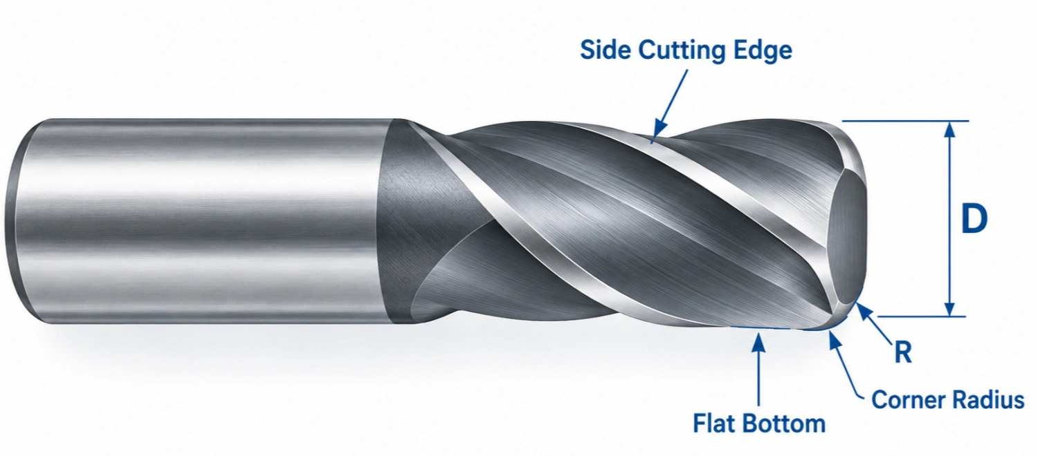
The corner radius is located between the bottom cutting edge and the side cutting edge. It affects the geometry created where the machined floor transitions into the side wall.
If you need a broader explanation of the cutter geometry and common applications, vedea Ce este o freză cu nas de taur?
For radius selection, cu toate acestea, the most important question is not simply “What is R?” It is:
Which finished feature is this R expected to produce or accommodate?
Start with the Required Part Geometry
Identify Which Radius the Drawing Controls
Do not assume that every radius dimension shown on a drawing should become the corner radius of the bull nose end mill.
First identify the feature controlled by the drawing dimension.
A specified radius may refer to:
- a finished bottom-to-wall transition;
- an internal corner visible in the XY plane;
- a curved profile feature;
- an edge transition;
- or another local feature on the part.
The location of the dimension matters.
If the radius controls the transition between a machined floor and side wall, the bull nose tool corner radius may be directly relevant.
If the dimension describes an XY-plane pocket corner or another profile, diametrul tăietorului, calea sculei, alocația de prelucrare, and other geometry may also affect how that feature is produced.
Din acest motiv, the drawing radius and the tool radius should not automatically be treated as the same value.
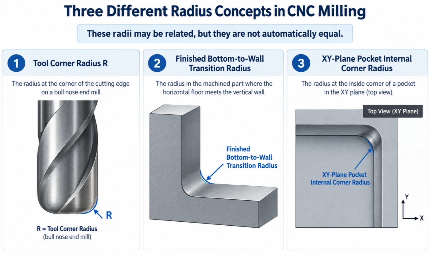
Distinguish Three Different Radius Concepts
Three different radius concepts can appear in the same machining discussion.
| Radius Concept | What It Describes | Main Selection Relevance |
|---|---|---|
| Tool Corner Radius R | The radius on the cutting corner of the bull nose end mill | A tool specification |
| Finished Bottom-to-Wall Transition Radius | The finished radius between the machined floor and side wall | May be directly influenced by tool R, depending on the machining process |
| XY-Plane Pocket Internal Corner Radius | The internal corner seen from the top view of a pocket or profile | Often influenced by cutter diameter, calea sculei, acces, and remaining material |
These three radii may be related, but they are not automatically equal.
De exemplu, an XY pocket corner marked R5 does not automatically mean that a bull nose end mill with tool corner radius R5 should be selected. The R5 dimension may describe the plan-view corner produced by the cutter path rather than the floor-to-wall radius produced by the cutting corner.
This distinction should be confirmed before selecting the tool.
Check the Required Bottom-to-Wall Transition
The bull nose corner radius is especially relevant when the finished part requires a flat or stepped floor together with a radiused transition into the side wall.
Check whether the part requires:
- a specified floor-to-wall radius;
- a radiused lower corner in a cavity;
- a stepped feature with a defined lower transition;
- or a profile that can accommodate a radiused cutting corner.
If the tool corner radius directly forms the final transition, the selected R generally needs to suit the required finished geometry and tolerance.
Cu toate acestea, the final feature may also depend on machining allowance, calea sculei, operatii de finisare, or other process conditions. Prin urmare, the tool R should be confirmed as part of the complete machining plan rather than selected from the radius value alone.
Consider Cutter Diameter and Radius Together
D and R Are Separate but Related Dimensions
Diametrul tăietorului D and corner radius R are separate dimensions.
The cutter diameter determines the overall cutting width and influences whether the tool can enter the feature. The corner radius controls the local geometry at the cutting corner.
A single cutter diameter can be produced with different corner radii.
De exemplu, CutterBest’s confirmed standard series includes more than one R option for several cutter diameters. În același timp, the same corner radius can appear on cutters with different diameters.
This means there is no universal rule such as:
- R must equal a fixed percentage of D;
- one diameter always requires one radius;
- or a specific R is automatically the best choice for a specific D.
The required feature should determine the radius first, while the cutter diameter must still suit the machining area and access conditions.
Check Cutter Diameter and Feature Access
A correct R does not automatically make the whole cutter suitable.
The selected cutter diameter must also fit the feature.
Verifica:
- pocket or cavity width;
- access around walls and adjacent features;
- required cutting depth;
- atingerea instrumentului;
- interference with the workpiece or fixture;
- and the overall machine setup.
A cutter with the correct corner radius may still be unsuitable if the diameter is too large for the feature or the cutting length and reach cannot access the required area.
This is why D and R should be confirmed together rather than selected independently.
Representative Standard D/R Combinations
The examples below show confirmed standard diameter/corner-radius combinations from our 4-flute product series.
These are specification examples only. They are not a recommended radius chart, a fixed D/R rule, or a substitute for checking the part drawing, finished geometry, accesul la instrumente, machining requirement, and current product configuration.
| Cutter Diameter D | Confirmed Corner Radius Examples |
|---|---|
| Ø2 mm | R0.2 / R0.3 |
| Ø3 mm | R0.2 / R0.3 / R0.5 |
| Ø4 mm | R0.2 / R0.5 / R1 |
| Ø6 mm | R0.5 / R1 |
| Ø8 mm | R0.5 / R1 |
| Ø10 mm | R0.5 / R1 |
| Ø12 mm | R0.5 / R1 |
| Ø14 mm | R1 / R2 |
| Ø16 mm | R1 |
| Ø20 mm | R1 |
The table illustrates an important point: availability does not mean recommendation.
De exemplu, the presence of both R1 and R2 on a particular cutter diameter does not mean that one is universally better than the other. The correct choice depends on the feature that must be machined.
For additional product dimensions and available configurations, vedea Taur Nose End Mill.
What If the Standard Radius Does Not Match the Drawing?
First confirm what the drawing radius represents.
If it is an XY-plane internal corner or another profile dimension, changing the bull nose tool corner radius may not be the correct solution.
If the required radius is specifically the finished bottom-to-wall transition and the standard D/R combinations do not meet the requirement, a custom cutter may be considered.
When reviewing a custom bull nose end mill, the radius should not be confirmed in isolation. Other dimensions may also need to match the application, including:
- diametrul tăietorului;
- lungimea tăieturii;
- lungime totală;
- diametrul tijei;
- configurație flaut;
- coating or surface treatment;
- and other drawing requirements.
Custom configurations can be evaluated from the actual drawing and machining requirement.
If a standard option does not match the required geometry, send the drawing or required dimensions for confirmation.
Confirm the Complete Tool Requirement
Tool Length and Reach
After confirming D and R, check whether the cutter can physically reach the machining area.
Important dimensions may include:
- lungimea tăieturii;
- effective reach;
- lungime totală;
- diametrul tijei;
- and available clearance around the tool.
These dimensions describe different aspects of tool access and should not be treated as interchangeable.
A deeper cavity or recessed feature may require additional reach, while a longer tool may also change the rigidity of the machining setup.
The required dimensions should therefore follow the actual part and machine configuration rather than a standard length assumption.
Workpiece and Machining Requirements
The workpiece material and machining requirements also affect the final cutter configuration.
Depending on the application, the complete tool configuration may vary in:
- geometria flautului;
- coating or surface treatment;
- lungimea sculei;
- center-cutting design;
- or tolerance requirement.
These factors should be confirmed after the part geometry and radius requirement are understood.
The workpiece material alone should not be used to select a fixed corner radius. De exemplu, there is no universal rule that stainless steel, aluminiu, oțel matriță, or hardened steel must use a particular R value.
The required geometry remains the starting point.
When a Bull Nose Radius May Not Be the Right Geometry
When the Drawing Requires a Sharp Corner
If the required feature needs a sharp cutting-corner result instead of a radiused bottom-to-wall transition, changing from one bull nose radius to another may not solve the problem.
În acest caz, the first decision is whether a bull nose cutter is the correct tool geometry at all.
For that comparison, vedea Nasul de taur vs moara plată.
When the Feature Requires a Fully Rounded Profile
A bull nose end mill keeps a flat cutting bottom and adds a radius at the cutting corners.
It does not have the fully rounded cutting end of a ball nose end mill.
If the required feature includes a continuous rounded bottom, spherical surface, or another geometry better suited to a fully rounded cutting end, another cutter type may be more appropriate.
For the geometry difference, vedea Moara de capăt cu nas de taur vs moara de capăt cu nas cu bilă.
FAQ
How do I choose a bull nose end mill radius?
Start by identifying which feature the drawing radius controls.
If the radius applies to the finished bottom-to-wall transition, confirm the required finished geometry and tolerance. Then check the cutter diameter, feature access, atingerea instrumentului, and available D/R combinations.
The final tool should match the complete machining requirement rather than a general radius rule.
Does the tool radius have to match the part radius?
Nu întotdeauna.
If the tool corner radius directly forms the final bottom-to-wall transition, the tool R generally needs to suit that finished geometry and tolerance.
Cu toate acestea, a drawing radius may describe an XY internal corner, another profile feature, alocația de prelucrare, or geometry produced by a different toolpath or later operation. In those cases, the drawing radius should not automatically be used as the bull nose tool R.
Can the same cutter diameter have different corner radii?
Da.
De exemplu, CutterBest’s confirmed 4-flute series includes Ø4 mm cutters with R0.2, R0.5, and R1 options.
This does not mean that one of these radii is the recommended choice for every Ø4 mm application. The required feature determines which R should be considered.
What if the required radius is not a standard size?
First confirm that the specified radius actually refers to the feature controlled by the tool corner radius.
If a non-standard tool R is required, CutterBest can evaluate a custom configuration from the drawing, dimensiunile cerute, materialul piesei de prelucrat, și cerințele de prelucrare.
Custom feasibility, dimensiuni, and other requirements should be confirmed for the specific application.
Is a larger corner radius always better?
Nu.
A larger corner radius is not automatically the better choice. The selected R must first suit the required finished geometry.
Diametrul tăietorului, feature access, atingerea instrumentului, machining requirement, and the complete cutter configuration also need to be considered.
Concluzie
Choosing a bull nose end mill radius starts with the part, not with a universal D/R formula.
First identify which feature the drawing radius controls. Then determine whether the requirement relates to the tool corner radius, the finished bottom-to-wall transition, or an XY-plane internal corner.
After the geometry is clear, confirm the cutter diameter, R value, accesul la instrumente, ajunge, and standard or custom configuration.
A standard D/R combination can show what configurations are available, but it does not determine which radius is correct for the part.
If you need help confirming a cutter for a specific component, send your drawing or sketch, dimensiunile cerute, materialul piesei de prelucrat, și cerințele de prelucrare pentru revizuire.