 Cortadores de fresagem de precisão,Ferramentas de corte para usinagem CNC de todos os materiais

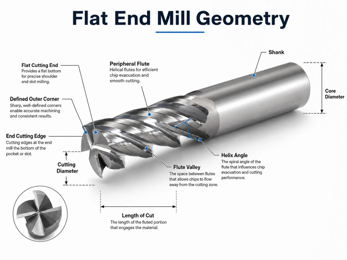
Uma fresa de topo plano é uma fresa rotativa com um perfil de corte plano e cantos externos definidos. Suas arestas de corte finais removem material próximo à parte inferior da ferramenta, enquanto os canais periféricos cortam ao longo da lateral da peça de trabalho. Esta geometria ajuda a criar superfícies planas, paredes retas, e transições claras de baixo para parede.
No entanto, o perfil final por si só não determina o desempenho da usinagem. Contagem de flauta, diâmetro do núcleo, ângulo de hélice, comprimento de corte, preparação de borda, revestimento, e o balanço da ferramenta afetam o comportamento da fresa sob carga.
Duas ferramentas com o mesmo diâmetro de corte podem, portanto, produzir resultados muito diferentes. Um projeto com baixo número de canais pode evacuar cavacos de alumínio de forma eficiente, enquanto uma fresa com maior contagem de canais pode fornecer a rigidez necessária para usinagem ou acabamento de aço.
Para materiais de ferramentas disponíveis, dimensões, contagens de flauta, revestimentos, e opções personalizadas, revise nosso fresa de topo plano página do produto.
Geometria da fresa de topo plano: Os recursos que importam
Uma fresa de topo plano é mais do que uma fresa com fundo plano. Seu desempenho depende da relação entre os cantos de corte, vales de flauta, essencial, ângulo de hélice, arestas de corte finais, e flautas periféricas.
Extremidade de corte plana e cantos externos
A extremidade de corte tem um perfil geralmente plano. Seus cantos externos conectam as arestas de corte finais com as arestas de corte periféricas.
Um canto agudo cria uma transição clara entre a parede inferior e lateral. No entanto, também concentra o estresse de corte. O lascamento de cantos torna-se mais provável quando a configuração apresenta desvio excessivo, saliência longa, corte interrompido, ou envolvimento agressivo.
Quando o desenho da peça permite um raio de canto, um design de nariz de touro pode fortalecer o canto de corte. Quando o componente requer uma transição interna mais nítida, um perfil de extremidade plana continua sendo a opção mais adequada.
Arestas de corte finais e periféricas
As arestas de corte finais removem material próximo à parte inferior da ferramenta. Sua geometria detalhada também afeta a forma como a fresa entra na peça de trabalho.
Não assuma que toda fresa de topo plano pode mergulhar diretamente em material sólido. Alguns projetos suportam mergulho controlado, rampa, ou entrada helicoidal. Outras ferramentas podem exigir entrada lateral ou uma abertura existente.
Arestas de corte periféricas correm ao longo do diâmetro externo. Eles influenciam a precisão da parede lateral, ação de corte radial, formação de cavacos, forças de corte, e acabamento superficial.
Vale da flauta e diâmetro do núcleo
O vale do canal oferece espaço para o fluxo de cavacos. Enquanto isso, o núcleo é o material sólido que suporta as arestas de corte.
Isso cria uma compensação prática:
- Vales de canais maiores melhoram a evacuação de cavacos.
- Um núcleo maior aumenta a rigidez da ferramenta.
- Mais arestas de corte podem melhorar a produtividade ou a qualidade da superfície.
- Muitos canais podem causar acúmulo de cavacos em ranhuras profundas.
Uma contagem de canais mais baixa é frequentemente selecionada quando o volume de cavacos é alto. Uma contagem de canais mais alta é mais comum quando o engate radial é menor e a rigidez ou o desempenho de acabamento são mais importantes.
Ângulo de hélice
O ângulo da hélice controla o quão gradualmente a aresta de corte entra no material e como as forças de corte se movem através da fresa.
Os pontos de partida típicos incluem:
- Cerca de 35°–40° para usinagem geral e arestas de corte mais resistentes
- Cerca de 45° para corte e acabamento mais suaves
- Ângulos de hélice mais altos para melhor fluxo de cavacos, com maior força axial
- Ângulos de hélice mais baixos para bordas mais fortes e menor força de elevação
Esses valores não são regras fixas. Diâmetro da ferramenta, material da peça, contagem de flauta, noivado, e a rigidez da máquina ainda determinam a geometria final.
Comprimento de corte e balanço da ferramenta
Arestas de corte longas melhoram o alcance, mas eles reduzem a rigidez. Como resultado, o cortador se torna mais sensível à deflexão, acabar, e vibração.
Use o menor comprimento prático de canal e balanço da ferramenta sempre que possível. Um suporte rígido, baixo desvio, e uma haste forte também melhoram a estabilidade.
Uma flauta curta, o design de pescoço longo muitas vezes pode atingir um recurso profundo com melhor rigidez do que um cortador longo totalmente canelado.
Como uma fresa plana corta?
O fuso gira a fresa enquanto a máquina CNC controla seu movimento em relação à peça de trabalho. Cada aresta de corte entra no material, forma um chip, e sai da zona de corte.
As bordas finais atuam perto da parte inferior da ferramenta. Enquanto isso, as estrias periféricas cortam a lateral do recurso. A distribuição real da carga depende da profundidade axial, engate radial, método de entrada, e percurso.
Formação e evacuação de chips
Cada aresta de corte corta um cavaco da peça de trabalho. A flauta deve então levar o cavaco embora antes que a próxima borda alcance a mesma área.
A má evacuação dos cavacos pode causar:
- Recorte de cavacos
- Calor excessivo
- Borda construída
- Danos de ponta
- Mau acabamento superficial
O controle de cavacos torna-se especialmente importante durante a usinagem de bolsões profundos, ranhura de largura total, usinagem de alumínio, e outras operações de corte de alto volume.
Explosão de ar, refrigerante, ou outro método adequado de remoção de cavacos deve corresponder ao material e ao processo de usinagem. O objetivo principal é simples: os cavacos devem sair da zona de corte de forma rápida e consistente.
Escolhas práticas de geometria por material
As tabelas a seguir fornecem pontos de partida práticos. A seleção final ainda depende do grau do material, dureza, diâmetro da ferramenta, condição da máquina, método de refrigeração, e percurso.
Geometria típica por material da peça
| Peça de trabalho | Geometria Típica | Risco Principal |
| Alumínio e ligas não ferrosas | 2–3 flautas, grandes vales de flauta, bordas afiadas ou polidas | Soldagem de cavacos e aresta postiça |
| Aço geral | 4 ou mais flautas com um núcleo mais forte | Aquecer, vestir, e deflexão |
| Aço inoxidável | Ferramenta rígida, borda estável, envolvimento controlado | Calor e endurecimento por trabalho |
| Ferro fundido | Substrato resistente ao desgaste e borda reforçada | Desgaste abrasivo |
| Aço endurecido | Núcleo forte, saliência curta, borda reforçada | Lascas e desgaste rápido |
Direção Típica do Revestimento
| Peça de trabalho | Direção do Revestimento | Foco de seleção |
| Alumínio e ligas não ferrosas | Não revestido, DLC, TiB2, ou outra opção adequada | Baixo atrito e adesão reduzida |
| Aço geral | TiAlN, AlTiN, ou revestimento específico da aplicação | Resistência ao calor e ao desgaste |
| Aço inoxidável | Revestimento resistente ao calor selecionado por tipo de material | Corte estável e controle de calor |
| Ferro fundido | Revestimento resistente ao desgaste | Resistência à abrasão |
| Aço endurecido | Revestimento de alta temperatura selecionado pela HRC real | Força da borda e resistência ao calor |
Para alumínio, espaço para fichas, bordas afiadas, e baixa adesão do material são geralmente as principais prioridades. Dois- ou projetos de três canais geralmente oferecem mais espaço para evacuação de cavacos.
Para aço em geral, rigidez e resistência ao calor geralmente se tornam mais importantes. Quatro ou mais canais podem funcionar bem quando a carga de cavacos e o engate radial permanecem sob controle.
Para aço endurecido, sempre forneça a dureza real. CDH 45, CDH 55, e CDH 65 requerem materiais de ferramentas diferentes, preparações de borda, revestimentos, e parâmetros de corte.
Preparação de Revestimento e Borda
Ferramentas não revestidas ou polidas geralmente são adequadas para alumínio, cobre, e outros materiais não ferrosos. Sua afiada, superfícies de baixo atrito ajudam a reduzir arestas postiças.
Os revestimentos TiAlN e AlTiN são amplamente utilizados para aço, aço inoxidável, aço para ferramentas, e outras aplicações intensivas em calor. No entanto, a seleção do revestimento ainda deve corresponder ao grau exato da peça e às condições de usinagem.
DLC e revestimentos similares de baixo atrito são frequentemente considerados para alumínio e outros materiais não ferrosos porque podem reduzir a adesão do material.
A preparação das bordas é tão importante quanto o revestimento. Uma aresta muito afiada reduz a força de corte, mas pode lascar durante cortes duros ou interrompidos. Um afiar leve fortalece a borda, embora também aumente a força de corte.
Guia de solução de problemas de fresas planas
| Problema | Causa provável | Correção Prática |
| Conversa | Longa saliência, retenção fraca, ou alto engajamento | Encurte a saliência e reduza o envolvimento |
| Parede cônica | Deflexão da ferramenta ou carga de corte excessiva | Use uma ferramenta mais curta ou adicione uma passada de acabamento |
| Embalagem de chips | Muitos canais ou má remoção de cavacos | Use menos canais e melhore o escoamento de cavacos |
| Borda construída | Borda inadequada, revestimento, ou carga de chip | Use uma borda mais afiada e lubrificação adequada |
| Lascas de canto | Acabar, impacto, ou corte interrompido | Reduza o choque de entrada e verifique o desvio |
| Acabamento ruim | Conversa, recortar, ou deflexão | Melhore a rigidez e remova cavacos de forma eficaz |
Como reduzir a vibração e a deflexão
Comece com a configuração mecânica:
- Reduza o balanço da ferramenta.
- Use o menor comprimento de corte prático.
- Melhore a rigidez do suporte e da peça de trabalho.
- Reduza o engate radial ou axial.
- Evite o envolvimento total repentino nos cantos internos.
- Deixe uma margem de acabamento controlada.
Não reduza o avanço para um valor extremamente baixo sem verificar a carga de cavacos. A alimentação muito lenta pode fazer com que a lâmina de corte esfregue em vez de cortar. Isso aumenta o calor e pode piorar o acabamento da superfície.
Como melhorar a evacuação de chips
Para slots profundos e alto volume de chips:
- Escolha menos flautas ou vales de flauta maiores.
- Direcionar ar ou líquido refrigerante para a zona de corte.
- Evite que os chips sejam cortados novamente.
- Reduza a profundidade axial quando os cavacos não puderem escapar.
- Considere a geometria do quebra-cavacos para cavacos longos.
Fresa de topo plano vs fresa de topo quadrado
Em muitos catálogos de fresas de topo sólidas, “fresa de topo plano” e “fresa de topo quadrada” descrevem a mesma geometria geral: uma extremidade de corte plana com cantos externos definidos.
Os termos enfatizam detalhes diferentes:
- “Flat” descreve o perfil inferior.
- “Quadrado” descreve o canto onde as arestas de corte finais e periféricas se encontram.
Os compradores ainda devem confirmar o desenho. Alguns fornecedores distinguem entre um canto agudo, um pequeno chanfro protetor, e um pequeno raio de canto.
Uma fresa de topo quadrada também é diferente de uma fresa de cantos a 90 graus. Uma fresa de canto quadrado descreve uma ferramenta ou sistema de fresamento projetado para produzir um canto de 90°. Ela pode usar pastilhas intercambiáveis e não se assemelhar a uma fresa de topo plana sólida.
Fresa de topo plano vs geometria de ponta de touro e ponta esférica
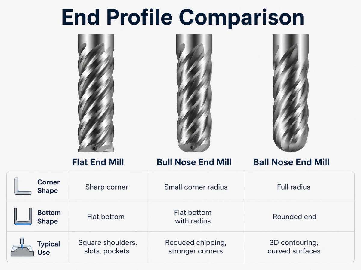
Plano, Nariz de touro, e comparação de nariz esférico
| Perfil da ferramenta | Geometria final | Efeito Principal |
| Fresa de topo plano | Extremidade plana com cantos definidos | Produz fundos planos e transições mais nítidas |
| Fresa de ponta de touro | Centro plano com raios de canto | Fortalece cantos e reduz lascas |
| Fresa de ponta esférica | Extremidade totalmente arredondada | Suporta usinagem de superfícies curvas e 3D |
Uma fresa de ponta arredondada fortalece o canto de corte, enquanto um perfil plano preserva uma transição interna mais nítida. Para uma comparação mais detalhada, ler nariz de touro vs fresa de topo plano.
Para geometrias de ponta totalmente arredondadas, revise nosso fresas de ponta esférica.
Quais informações você deve enviar a um fornecedor de ferramentas?
Uma recomendação profissional exige mais do que o diâmetro da ferramenta.
Envie as seguintes informações:
- Material da peça e classe exata
- Dureza do material, incluindo HRC quando aplicável
- Diâmetro de corte
- Comprimento da flauta
- Comprimento total
- Diâmetro da haste
- Alcance ou comprimento do pescoço necessário
- Contagem de flauta
- Operação de usinagem e método de entrada
- Condição de refrigeração ou corte a seco
- Tolerância necessária e acabamento superficial
- Quantidade do pedido
- Desenho de ferramenta ou desenho de peça
Esta informação ajuda o fornecedor a avaliar o material da ferramenta, geometria da flauta, ângulo de hélice, preparação de borda, revestimento, e rigidez.
Para dimensões fora do padrão ou ferramentas específicas da aplicação, revise nosso fresas de topo personalizadas serviço.
Perguntas frequentes
Qual é outro nome para uma fresa de topo plano?
Muitos fornecedores também usam o termo fresa de topo quadrado. Alguns catálogos usam fresa de fundo plano, embora o desenho deva confirmar a geometria real do canto.
Todas as fresas de topo plano são feitas de metal duro?
Não. O material e a construção da ferramenta podem ser selecionados de acordo com a peça de trabalho, máquina, volume de produção, condições de corte, e requisitos do cliente.
As fresas de topo plano podem ter contagens de canais diferentes?
Sim. Dois, três, quatro, seis, e contagens de flauta personalizadas são possíveis. A escolha correta depende do volume do chip, rigidez, noivado, material, e requisitos de acabamento superficial.
Toda fresa de topo plano é adequada para mergulho direto??
Não. O mergulho direto depende do centro e da geometria do corte final. Confirme se a ferramenta suporta mergulho, rampa, entrada helicoidal, entrada lateral, ou usinagem a partir de uma abertura existente.
Conclusão
Uma fresa de topo plano é definida por seu perfil de corte plano e cantos externos definidos. Seu desempenho depende da relação entre o vale da flauta, força central, ângulo de hélice, comprimento de corte, preparação de borda, revestimento, e balanço da ferramenta.
O resultado da usinagem também fornece dicas úteis. O Chatter aponta para instabilidade ou envolvimento excessivo. Paredes cônicas sugerem deflexão. Embalagem de cavacos indica evacuação deficiente. Danos nos cantos podem mostrar que a geometria da borda ou a carga de corte não correspondem ao trabalho.
A compreensão desses sinais ajuda os engenheiros a selecionar uma fresa mais adequada. Também fornece às equipes de compras as informações necessárias para solicitar um orçamento preciso.
Discuta seus requisitos de fresadora de topo plano
Revise nosso padrão e personalizado fresa de topo plano opções para diferentes materiais de ferramentas, tamanhos, contagens de flauta, ângulos de hélice, revestimentos, e condições de usinagem.
Por favor envie o material da sua peça, dureza, dimensões da ferramenta, operação de usinagem, quantidade, e desenho se disponível.
E-mail: sales@cutterbest.com