 Freze de precizie,Scule de tăiere pentru prelucrarea CNC a fiecărui material

To choose a finishing end mill, start with the surface and geometry the part must achieve. Compare tool options against the remaining stock, material, cutting contact and assembled tool reach. Keep the options that satisfy those constraints, record why others fail, and identify what still needs confirmation.
Finishing describes a machining stage. Pătrat, corner radius and ball nose tools can serve that stage, while manufacturers may also offer dedicated finishers for particular materials or tasks. This guide focuses on selecting a suitable solid carbide tool direction before confirming a specific model.
How to Choose a Finishing End Mill: Quick Decision Map
| Finishing task | Starting direction | Check before committing |
|---|---|---|
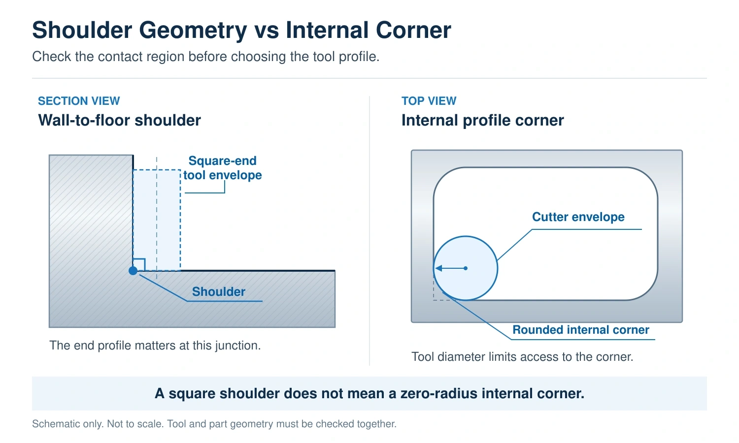
| Machine a flat floor and a specified square wall-to-floor shoulder | Evaluate a square-end tool | Confirm the permitted corner condition. A square shoulder does not establish a zero-radius internal corner in plan view. |
| Finish a side wall without cutting the bottom transition | Compare tools by their peripheral cutting geometry | Determine whether the end or corner radius will contact the part. A straight wall alone does not require a square-end tool. |
| Finish a rounded wall-to-floor transition using the tool end | Compare a corner radius tool with a separate transition-finishing operation | Check the local geometry, tool profile and toolpath for interference, overcutting and remaining stock. |
| Finish broad 3D surfaces containing small local details | Evaluate ball nose tooling and possible separate detail tools | Check whether one tool can reach every feature and whether dividing the work creates acceptable transitions. |
| Reach a deep or restricted surface | Select the profile first, then compare reach structures | Check cutting contact, drawing dimensions, mounted projection and clearance throughout the toolpath. |
Use the map to narrow the options. Final selection still requires a compatible tool configuration and a workable machining setup.
Define the Finished Feature and Acceptance Requirements
Identify the Surface and Inspection Requirements
Mark the surfaces included in the finishing operation. A pocket may contain a floor, ziduri drepte, rounded transitions and local details that need different cutting contacts.
For each critical area, identify the applicable requirement:
- Surface texture or a specified roughness parameter.
- Dimensiune, wall position or dimensional tolerance.
- Planeitatea, profile or another geometric requirement.
- Corner shape and permitted edge condition.
These requirements may lead to different tool choices. A visually smooth wall can still be outside its dimensional tolerance. De asemenea, a part that meets size requirements may fail its specified surface inspection.
If the drawing leaves an important transition or inspection requirement unclear, resolve it before selecting the final tool.
Check Which Part of the Tool Will Cut
Determine whether the operation uses the peripheral edges, the tool end, the corner region or a combination of them.
A square-end tool may suit a specified square wall-to-floor shoulder. When only the side wall is being finished, cu toate acestea, a corner radius tool may also be suitable if its rounded portion clears the finished geometry.
Keep two features separate: the shoulder seen in a wall-to-floor section and an internal corner seen from above. Cutter diameter limits access to the latter; an ordinary rotating end mill cannot produce every zero-radius internal profile corner.
For rounded transitions, the presence of a part radius makes a corner radius tool a candidate. It does not prove that the tool can generate the required surface with the proposed path. Pătrat, corner radius and ball profiles provide different contact geometries.
Check Remaining Stock, Cutting Edges and Runout Before Selection
Check Stock Uniformity and Local Engagement
Review what roughing or semi-finishing has actually left behind. Include corners, narrow areas and transitions where the previous tool may have left additional material.
An allowance that appears light along a straight wall may become substantially heavier at a corner. The finishing tool must either accommodate that change or follow a preparation operation that reduces it.
Also avoid assuming that less stock is always better. Remaining stock and chip thickness are different quantities. The planned engagement, hrana, material and cutting-edge condition must support effective cutting.
Where stock is excessive or uneven, consider a rest-machining or semi-finishing operation before final tool selection. Consistent finishing stock is an important part of the process; the appropriate amount depends on the application.
Decide Whether the Existing Tool Can Make the Final Pass
An end mill already used earlier in the process may remain suitable when its geometry, cutting condition and remaining capability match the final requirements.
Inspect the cutting edges for wear, chipping or material buildup. Check the assembled tool for runout as well: uneven flute engagement can change the load carried by individual edges.
Retain the existing tool only when those conditions support the finishing operation. Evaluate a separate tool when:
- Its profile cannot produce the specified feature.
- Edge damage or wear threatens the required result.
- The earlier operation leaves unsuitable or inconsistent stock.
- The final surface or dimensional requirement calls for a separately controlled tool condition.
A new cutter will still need suitable toolholding, workholding and engagement. If those conditions are unresolved, pause the selection rather than treating a tool change as the complete solution.
Verify Tool Reach in the Actual Assembly
Confirm Cutting Contact and Drawing Dimension References
Choose cutting length from the maximum axial contact required by the intended toolpath. Feature depth alone does not establish that contact length.
A deep cavity with a short finishing contact area may justify evaluating a relieved-neck tool. Compare its complete structure with a long-flute alternative before deciding.
| Dimension or condition | Decision it supports |
|---|---|
| Length of cut, or LOC | Whether sufficient cutting edge is available for the maximum axial contact |
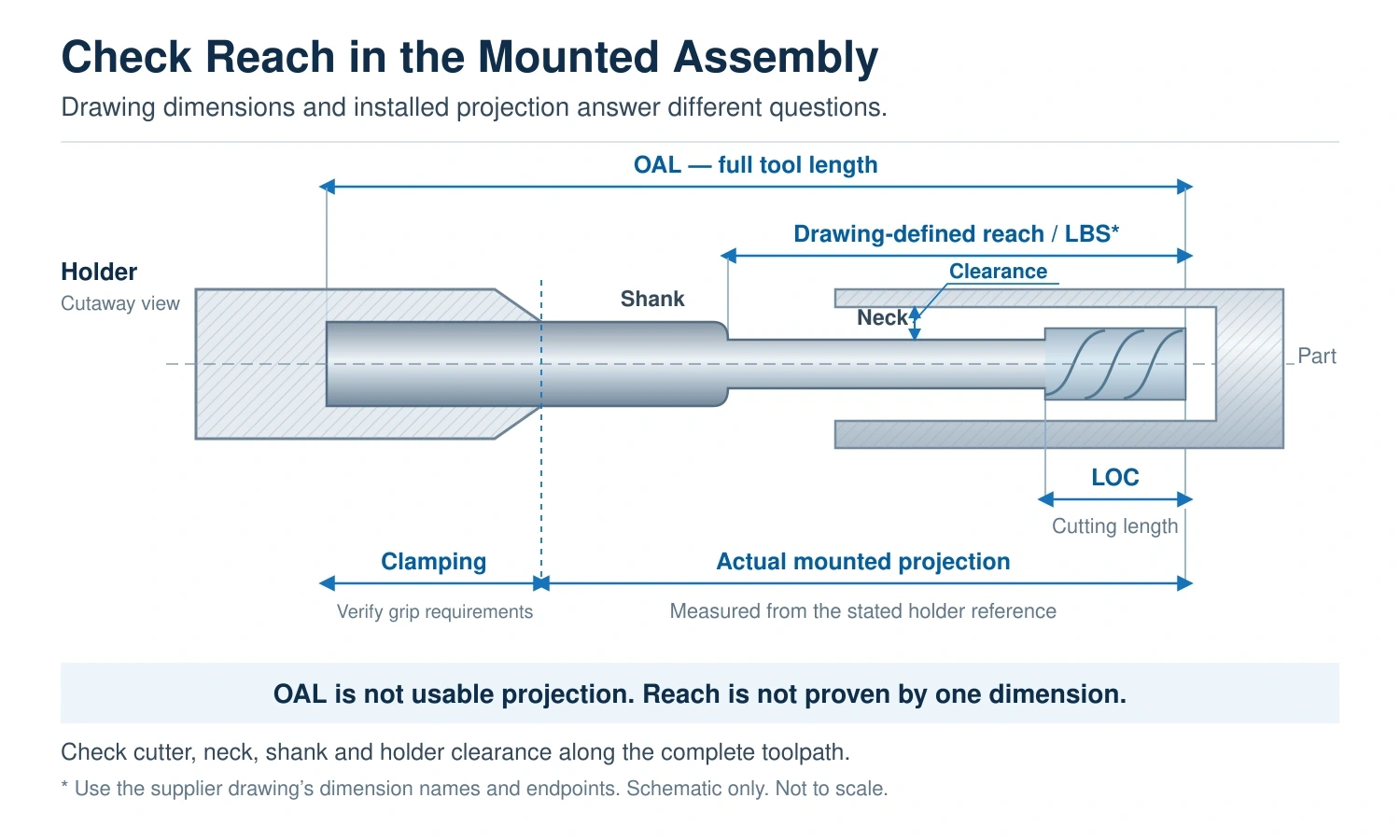
| Drawing-defined reach or length below shank | Whether the relevant tool section reaches the feature, using the drawing’s stated reference points |
| Lungime totală, or OAL | Whether the complete tool fits the intended assembly; it does not directly establish usable projection |
| Mounted tool projection | Whether the installed position provides access while meeting the holder’s clamping requirements |
| Tool and holder clearance | Whether the assembly avoids unintended contact throughout the programmed movement |
Read each supplier’s dimension definitions. A reach dimension, neck-segment length and length below shank should not be treated as interchangeable without checking their endpoints.
Check Projection and Clearance Along the Toolpath
Assess the tool in its mounted position. State the reference used for projection, such as the holder nose, and check the required clamping engagement.
Then examine the complete path. Intrare, finisare perete, corner movement and withdrawal may create different clearance conditions for the neck, shank and holder.
Compare neck diameter, individual section lengths and actual projection when assessing stability. A long-neck tool does not automatically provide a more rigid solution.
If neither candidate can reach the surface with acceptable support and clearance, revisit the fixture, machining orientation or operation sequence.
Match Flute and Edge Geometry to Material and Engagement
Compare Chip Space with Additional Cutting Edges
Compare actual tool designs at the required diameter and cutting length. Flute count influences the available chip space, but it does not describe the complete geometry.
A tool with more cutting edges may be worth evaluating for controlled finishing engagement. That option remains conditional on chip evacuation, tool structure and the machining setup. Material and operation both influence the choice.
Where chips cannot leave the cutting area reliably, increasing flute count simply to add cutting contacts is a weak selection basis. Resolve the evacuation requirement and compare the candidates again.
For the detailed trade-offs, vezi noastre end mill flute count comparison.
Confirm Material-Specific Geometry and Coating
Use the actual workpiece grade, heat-treatment condition and known hardness when comparing configurations.
Pentru aluminiu, assess the cutting edge and chip-handling geometry. Pentru oțel, stainless steel or titanium, review the relevant material-specific design rather than transferring one configuration across all applications.
Confirm the coating together with the carbide grade, edge preparation and intended cutting conditions. A coating name alone cannot establish suitability.
Noastre carbide end mill selection by material guide covers the broader material-based choices. Here, the purpose is to verify that each candidate remains suitable for the particular finishing task.
Finishing End Mill Selection Examples
The following examples are hypothetical. They demonstrate selection decisions without prescribing a cutter model, cutting parameter or guaranteed machining result.
Aluminum Side-Wall Finishing with Restricted Chip Evacuation
Known conditions: The operation finishes an aluminum side wall. Chips have limited space to leave the cutting area.
Option A: An aluminum-suitable tool prioritizing chip space and evacuation.
Option B: An aluminum-suitable tool providing more cutting edges, with its own flute-space limits.
Compare the available chip space, actual engagement and delivery of coolant or air. If Option B cannot evacuate chips under those conditions, set it aside even if its additional edges appear attractive for finishing.
Option A remains a candidate only if its geometry and support suit the required wall contact. Fewer flutes alone do not establish suitability.
Selection outcome: Prioritize the candidate that can handle the chips while satisfying the wall-finishing requirements. Pause if the engagement or evacuation conditions are unknown; there is not yet enough information to choose between the two designs.
A Flat-Bottom Cavity with a Rounded Transition
Known conditions: The cavity contains a flat floor and a specified rounded transition to the wall.
Option A: A corner radius tool that machines the transition through end and corner contact.
Option B: Separate operations for the floor, wall or transition, using suitable tools for each region.
If geometrically valid, Option A may reduce the need to blend separately machined regions. Option B allows each region to use a suitable tool and cutting contact, but requires checking where those regions meet.
Check Option A’s swept profile against the local part geometry. Keep it only if the proposed path avoids overcutting, provides clearance and leaves manageable residual material.
The tool radius need not automatically equal the part radius. Equally, a different radius is not automatically workable. The profile and path must be assessed together.
Selection outcome: Retain a geometrically valid route. Pause when the transition geometry or proposed toolpath is unavailable; the presence of an R dimension alone cannot settle the choice.
A Deep Cavity with a Short Cutting Contact Area
Known conditions: The target surface is deep inside the part, but the intended finishing pass uses only a short axial section of cutting edge.
Option A: A long-flute tool proposed for the required cavity reach.
Option B: A shorter cutting section with a reach structure intended to clear the surrounding geometry.
Compare both assemblies at the projection needed for the actual operation. Check cutting contact, diametrul gâtului, section lengths, holder clearance and clamping requirements.
Retain the long-flute candidate if its actual geometry and mounted position meet the contact, support and clearance requirements. Defer it if its extra cutting length offers no useful benefit and compromises support. The shorter-cutting-section candidate must pass the same checks.
Selection outcome: Prefer the candidate that provides the required contact and access with suitable support. If neither does, revisit the setup or operation sequence. Do not keep extending the tool until it merely reaches the bottom.
A Broad 3D Surface with Small Local Features
Known conditions: A broad curved surface includes small details that limit the size of the tool able to enter them.
Option A: One small ball nose tool machines the entire surface and all accessible details.
Option B: A larger suitable ball nose tool covers the broad regions, followed by a smaller ball nose tool for local features.
Using one small tool avoids an extra tool change and simplifies transitions between regions. Check whether its reach, rigidity and toolpath suit the full surface.
Where local geometry permits, a larger ball nose tool may allow a wider stepover for the same theoretical scallop height and reduce the number of passes. Verify this against local curvature and the CAM strategy; it does not guarantee a shorter total cycle or the specified surface roughness.
Option B adds tool changes, residual-stock management and transition checks. Defer it if the larger tool cannot clear its assigned region or the region boundaries cannot meet the required surface continuity.
Ball nose contact conditions affect effective cutting diameter, so nominal diameter alone is insufficient for the comparison.
Selection outcome: Compare the complete operation, including local access and region boundaries. Pause if the remaining stock or required surface continuity cannot be verified. Once the ball nose route is established, use our ball nose end mill selection guide to review its configuration.
Record the Selection, Rejected Options and Open Questions
Keep a short decision record before requesting a specific tool recommendation. The deep-cavity example could produce the following:
| Decision item | Recorded conclusion |
|---|---|
| Finishing task | Reach and finish the specified cavity surface with a short axial cutting contact |
| Candidates compared | Long-flute tool and short-cutting-section reach design |
| Preferred direction | Evaluate the reach design further, subject to its neck structure and mounted clearance |
| Rejected or deferred option | Defer the long-flute candidate if its extra cutting length provides no useful benefit and compromises the required support |
| Open questions | Confirm workpiece condition, maximum contact length, dimension references, holder position and available clearance |
| Verification needed | Confirm the proposed configuration with the supplier, then verify the specified surface, dimensional and geometric requirements using the applicable inspection methods. |
This record distinguishes a supported direction from a confirmed manufacturing specification. It also shows which missing information could change the decision.
If a critical clearance, material condition or acceptance requirement remains unknown, keep the selection open until it is resolved.
Need Help Selecting a Finishing End Mill?
Explorați-ne finishing end mill options. Share your tool reference or drawing and machining requirements by E-mail sau WhatsApp for application review.