 Прецизионные фрезы,Режущие инструменты для обработки любого материала с ЧПУ

Фреза с плоским концом — это вращающаяся фреза с плоским профилем резания и четко выраженными внешними углами.. Его концевые режущие кромки удаляют материал вблизи нижней части инструмента., при этом периферийные канавки режут вдоль боковой поверхности заготовки. Эта геометрия помогает создавать плоские поверхности., прямые стены, и четкие переходы от дна к стене.
Однако, сам по себе конечный профиль не определяет производительность обработки. Количество флейт, диаметр сердечника, угол спирали, длина резки, подготовка кромок, покрытие, и вылет инструмента влияют на поведение фрезы под нагрузкой..
Таким образом, два инструмента с одинаковым диаметром резания могут давать совершенно разные результаты.. Конструкция с малым количеством канавок позволяет эффективно удалять алюминиевую стружку., в то время как фреза с большим количеством канавок может обеспечить жесткость, необходимую для обработки или чистовой обработки стали..
Для доступных инструментальных материалов, размеры, Количество флейт, покрытия, и пользовательские опции, просмотрите наш плоская концевая фреза страница продукта.
Геометрия плоскоконцевой фрезы: Особенности, которые имеют значение
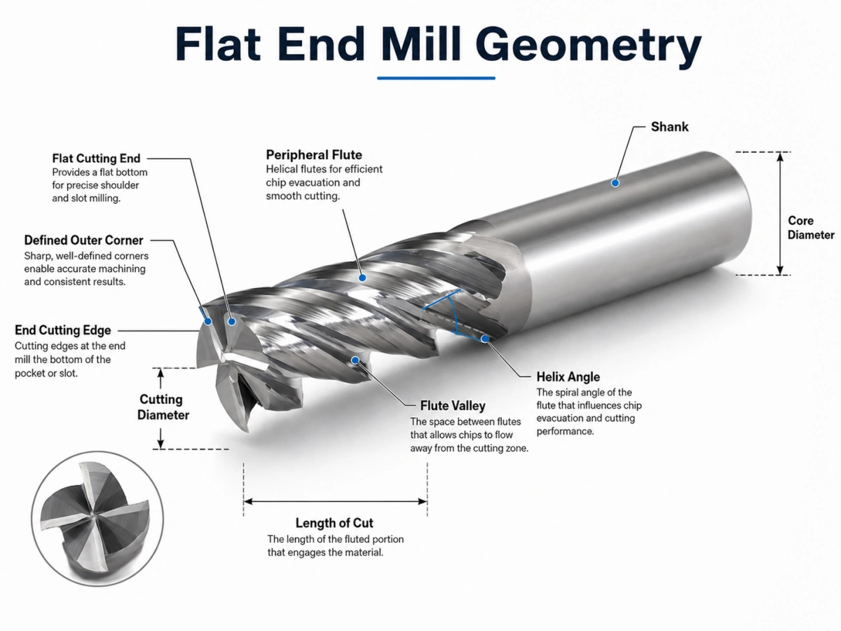
Плоская концевая фреза — это больше, чем фреза с плоским дном.. Его производительность зависит от соотношения между углами резки., долины флейты, основной, угол спирали, концевые режущие кромки, и периферийные флейты.
Плоский режущий конец и внешние углы
Режущий конец имеет, как правило, плоский профиль.. Его внешние углы соединяют концевые режущие кромки с периферийными режущими кромками..
Острый угол создает четкий переход между дном и боковой стенкой.. Однако, он также концентрирует сокращающийся стресс. Угловые сколы становятся более вероятными, если установка имеет чрезмерное биение., длинный свес, прерывистая резка, или агрессивное взаимодействие.
Если на чертеже детали разрешен угловой радиус, конструкция бычьего носа может усилить режущий угол. Когда компонент требует более резкого внутреннего перехода, профиль с плоским торцом остается более подходящим вариантом.
Концевые и периферийные режущие кромки
Концевые режущие кромки удаляют материал вблизи нижней части инструмента.. Их детальная геометрия также влияет на то, как фреза входит в заготовку..
Не думайте, что каждая фреза с плоским концом может погружаться непосредственно в твердый материал.. Некоторые конструкции поддерживают контролируемое погружение., нарастание, или винтовой вход. Для других инструментов может потребоваться боковой вход или существующее отверстие..
Периферийные режущие кромки проходят по наружному диаметру.. Они влияют на точность боковой стенки, радиальное режущее действие, образование стружки, силы резания, и качество поверхности.
Долина канавки и диаметр сердечника
Канавка обеспечивает пространство для отвода стружки.. Тем временем, сердцевина — это твердый материал, поддерживающий режущие кромки.
Это создает практический компромисс:
- Увеличенные канавки канавок улучшают эвакуацию стружки..
- Увеличенный сердечник повышает жесткость инструмента..
- Большее количество режущих кромок может повысить производительность или качество поверхности..
- Слишком большое количество канавок может привести к застреванию стружки в глубоких пазах..
Меньшее количество канавок часто выбирается при большом объеме стружки.. Большее количество канавок встречается чаще, когда радиальное зацепление меньше, а жесткость или качество чистовой обработки имеют большее значение..
Угол спирали
Угол спирали контролирует, насколько постепенно режущая кромка входит в материал и как силы резания проходят через фрезу..
Типичные отправные точки включают в себя:
- Около 35–40° для общей обработки и более прочных режущих кромок.
- Около 45° для более плавной резки и чистовой обработки.
- Больший угол спирали для улучшения отвода стружки, с большей осевой силой
- Меньшие углы спирали для более прочных кромок и меньшей подъемной силы
Эти ценности не являются фиксированными правилами.. Диаметр инструмента, материал заготовки, счет флейты, обручение, и жесткость машины по-прежнему определяют окончательную геометрию.
Длина резки и вылет инструмента
Длинные режущие кромки улучшают радиус действия, но они снижают жесткость. Как результат, фреза становится более чувствительной к отклонению, закончиться, и вибрация.
По возможности используйте наименьшую практическую длину канавок и вылет инструмента.. Жесткий держатель, низкое биение, и прочный хвостовик также улучшает стабильность.
Короткая флейта, конструкция с длинной шейкой часто позволяет достичь глубокого элемента с большей жесткостью, чем длинная фреза с полностью рифлеными канавками..
Как режется фреза с плоским концом?
Шпиндель вращает фрезу, а станок с ЧПУ контролирует ее движение относительно заготовки.. Каждая режущая кромка входит в материал, образует чип, и покидает зону резки.
Концевые кромки действуют вблизи нижней части инструмента.. Тем временем, периферийные канавки разрезают боковую часть элемента. Фактическое распределение нагрузки зависит от осевой глубины., радиальное зацепление, метод входа, и траектория инструмента.
Формирование и эвакуация стружки
Каждая режущая кромка срезает стружку с заготовки.. Затем канавка должна унести стружку до того, как следующая кромка достигнет той же области..
Плохая эвакуация стружки может привести к:
- Перерезка чипа
- Чрезмерное тепло
- Застроенный край
- Ультрасовременный урон
- Плохое качество поверхности
Контроль стружки становится особенно важным при обработке глубоких карманов., прорезь на всю ширину, обработка алюминия, и другие крупномасштабные операции по резке.
Воздушный взрыв, охлаждающая жидкость, или другой подходящий метод удаления стружки должен соответствовать материалу и процессу обработки.. Основная цель проста: стружка должна покидать зону резания быстро и стабильно.
Практический выбор геометрии в зависимости от материала
В следующих таблицах представлены практические отправные точки.. Окончательный выбор по-прежнему зависит от марки материала., твердость, диаметр инструмента, состояние машины, метод подачи охлаждающей жидкости, и траектория инструмента.
Типичная геометрия в зависимости от материала заготовки
| Заготовка | Типичная геометрия | Основной риск |
| Алюминий и цветные сплавы | 2–3 флейты, большие долины флейт, острые или полированные края | Сколы и наросты на кромках |
| Общая сталь | 4 или несколько флейт с более прочным сердечником | Нагревать, носить, и отклонение |
| Нержавеющая сталь | Жесткий инструмент, стабильный край, контролируемое взаимодействие | Тепловая и деформационная закалка |
| Чугун | Износостойкая подложка и усиленный край | Абразивный износ |
| Закаленная сталь | Сильное ядро, короткий свес, усиленный край | Сколы и быстрый износ |
Типичное направление нанесения покрытия
| Заготовка | Направление покрытия | Фокус выбора |
| Алюминий и цветные сплавы | Без покрытия, DLC, ТиБ2, или другой подходящий вариант | Низкое трение и уменьшенная адгезия |
| Общая сталь | TiAlN, Алтын, или покрытие для конкретного применения | Теплостойкость и износостойкость |
| Нержавеющая сталь | Термостойкое покрытие, выбранное по марке материала | Стабильная резка и контроль нагрева |
| Чугун | Износостойкое покрытие | Устойчивость к истиранию |
| Закаленная сталь | Высокотемпературное покрытие, выбранное настоящим HRC | Прочность кромки и термостойкость |
Для алюминия, пространство чипа, острые края, и низкая адгезия материала обычно являются основными приоритетами.. Два- или конструкции с тремя канавками часто обеспечивают больше места для эвакуации стружки.
Для общей стали, жесткость и термостойкость обычно становятся более важными. Четыре или более канавок могут хорошо работать, когда нагрузка на стружку и радиальное зацепление остаются под контролем..
Для закаленной стали, всегда указывайте фактическую твердость. HRC 45, HRC 55, и СПЧ 65 требуют различных инструментальных материалов, подготовка кромок, покрытия, и параметры резки.
Покрытие и подготовка кромок
Инструменты без покрытия или полированные часто подходят для алюминия., медь, и другие цветные материалы. Их острый, поверхности с низким коэффициентом трения помогают уменьшить наросты на кромке.
Покрытия TiAlN и AlTiN широко используются для стали., нержавеющая сталь, инструментальная сталь, и другие теплоемкие применения. Однако, Выбор покрытия по-прежнему должен точно соответствовать марке заготовки и условиям обработки..
DLC и аналогичные покрытия с низким коэффициентом трения часто рассматриваются для алюминия и других цветных металлов, поскольку они могут уменьшить адгезию материала..
Подготовка кромок имеет такое же значение, как и покрытие.. Очень острая кромка снижает силу резания, но может привести к сколам при жесткой или прерывистой резке.. Легкая заточка укрепляет кромку, хотя это также увеличивает силу резания.
Руководство по устранению неполадок фрез с плоским концом
| Проблема | Вероятная причина | Практическая коррекция |
| Болтовня | Длинный свес, слабый холдинг, или высокая вовлеченность | Уменьшите вылет и уменьшите зацепление |
| Коническая стена | Отклонение инструмента или чрезмерная нагрузка резания | Используйте более короткий инструмент или добавьте чистовой проход. |
| Упаковка чипов | Слишком много канавок или плохой отвод стружки. | Используйте меньше канавок и улучшите эвакуацию стружки |
| Застроенный край | Неподходящий край, покрытие, или загрузка чипа | Используйте более острую кромку и подходящую смазку. |
| Угловой скол | Закончиться, влияние, или прерывистая резка | Уменьшите входной удар и проверьте биение |
| Плохая отделка | Болтовня, перекройка, или отклонение | Повышение жесткости и эффективное удаление стружки |
Как уменьшить вибрацию и отклонение
Начнём с механической настройки.:
- Уменьшить вылет инструмента.
- Используйте самую короткую практическую длину резки..
- Улучшите жесткость держателя и заготовки..
- Уменьшите радиальное или осевое зацепление.
- Избегайте внезапного полного зацепления во внутренних углах..
- Оставьте контролируемый припуск на чистовую обработку.
Не уменьшайте подачу до очень низкого значения, не проверив нагрузку на стружку.. Слишком медленная подача может привести к тому, что режущая кромка будет тереться, а не резаться.. Это увеличивает нагрев и может ухудшить качество поверхности..
Как улучшить эвакуацию стружки
Для глубоких слотов и большого объема чипов:
- Выбирайте меньше флейт или более крупные доли флейт..
- Направьте воздух или охлаждающую жидкость в зону резки..
- Предотвращение повторного разрезания стружки.
- Уменьшите осевую глубину, если стружка не может уйти.
- Учитывайте геометрию стружколома для длинной стружки.
Фреза с плоским концом против фрезы с квадратным концом
Во многих каталогах цельных концевых фрез., «Фреза с плоским концом» и «фреза с квадратным концом» описывают одну и ту же общую геометрию.: плоский режущий конец с четко выраженными внешними углами.
Термины подчеркивают разные детали:
- «Плоский» описывает нижний профиль..
- «Квадрат» описывает угол, где встречаются концевая и периферийная режущие кромки..
Покупатели все равно должны подтвердить рисунок. Некоторые поставщики различают острый угол, небольшая защитная фаска, и небольшой радиус угла.
Фреза с квадратным концом также отличается от фрезы с квадратным уступом.. Фреза с квадратным уступом представляет собой инструмент или фрезерную систему, предназначенную для изготовления уступа под углом 90 °.. В нем могут использоваться сменные пластины, и он может не напоминать цельную фрезу с плоским концом..
Фреза с плоским концом по сравнению с геометрией бычьего и сферического носа
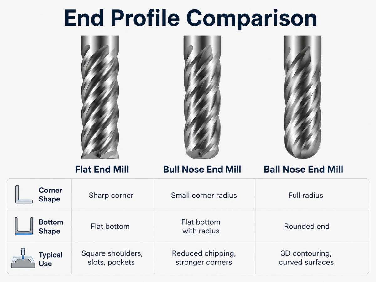
Плоский, Бычий нос, и сравнение шарового носа
| Профиль инструмента | Конечная геометрия | Основной эффект |
| Плоская концевая фреза | Плоский конец с определенными углами | Создает плоское дно и более резкие переходы. |
| Концевая фреза с бычьим носом | Плоский центр с угловыми радиусами | Укрепляет углы и уменьшает сколы |
| Шариковая концевая фреза | Полностью закругленный конец | Поддерживает обработку изогнутых и 3D поверхностей. |
Концевая фреза с бычьей головкой усиливает режущий угол, в то время как плоский профиль сохраняет более резкий внутренний переход. Для более детального сравнения, читать бычий нос против фрезы с плоским концом.
Для полностью закругленной геометрии режущих концов, просмотрите наш концевые фрезы со сферическим концом.
Какую информацию следует отправлять поставщику инструментов?
Профессиональная рекомендация требует большего, чем просто диаметр инструмента..
Отправьте следующую информацию:
- Материал заготовки и точный сорт
- Твердость материала, включая HRC, когда это применимо
- Диаметр резки
- Длина канавки
- Габаритная длина
- Диаметр хвостовика
- Требуемый вылет или длина шеи
- Количество флейт
- Операция обработки и метод ввода
- СОЖ или режим сухой резки
- Требуемый допуск и качество поверхности
- Количество заказа
- Чертеж инструмента или чертеж детали
Эта информация помогает поставщику оценить инструментальный материал., геометрия флейты, угол спирали, подготовка кромок, покрытие, и жесткость.
Для нестандартных размеров или специальных инструментов, просмотрите наш пользовательские концевые фрезы услуга.
Часто задаваемые вопросы
Как по-другому называется фреза с плоским концом?
Многие поставщики также используют термин «фреза с квадратным концом».. В некоторых каталогах используется концевая фреза с плоским дном., хотя чертеж должен подтверждать реальную геометрию угла.
Все фрезы с плоским концом изготовлены из твердого сплава??
Нет. Материал и конструкция инструмента могут быть выбраны в зависимости от заготовки., машина, объем производства, условия резания, и требования клиентов.
Могут ли фрезы с плоским концом иметь разное количество канавок??
Да. Два, три, четыре, шесть, и возможно индивидуальное количество флейт. Правильный выбор зависит от объема чипа., жесткость, обручение, материал, требования к качеству поверхности.
Любая ли фреза с плоским концом подходит для прямого врезания??
Нет. Прямое врезание зависит от геометрии центра и торца резания.. Подтвердите, поддерживает ли инструмент врезание, нарастание, винтовой вход, боковой вход, или обработка существующего отверстия.
Заключение
Плоская концевая фреза отличается плоским режущим профилем и определенными внешними углами.. Его производительность зависит от соотношения долины флейты, основная сила, угол спирали, длина резки, подготовка кромок, покрытие, и вылет инструмента.
Результат обработки также дает полезные подсказки.. Болтовня указывает на нестабильность или чрезмерную вовлеченность. Конические стены предполагают прогиб. Упаковка стружки указывает на плохую эвакуацию.. Повреждение углов может свидетельствовать о том, что геометрия кромки или нагрузка при резке не соответствуют заданию..
Понимание этих сигналов помогает инженерам выбрать более подходящий фрезер.. Это также дает командам закупок информацию, необходимую для запроса точного предложения..
Обсудите ваши требования к фрезе с плоским концом
Ознакомьтесь с нашими стандартами и заказами плоская концевая фреза варианты для различных инструментальных материалов, размеры, Количество флейт, углы спирали, покрытия, и условия обработки.
Пожалуйста, пришлите материал заготовки, твердость, размеры инструмента, операция механической обработки, количество, и рисунок, если есть.
Электронная почта: sales@cutterbest.com