 Precision Milling Cutters,Cutting Tools for CNC Machining Every Material

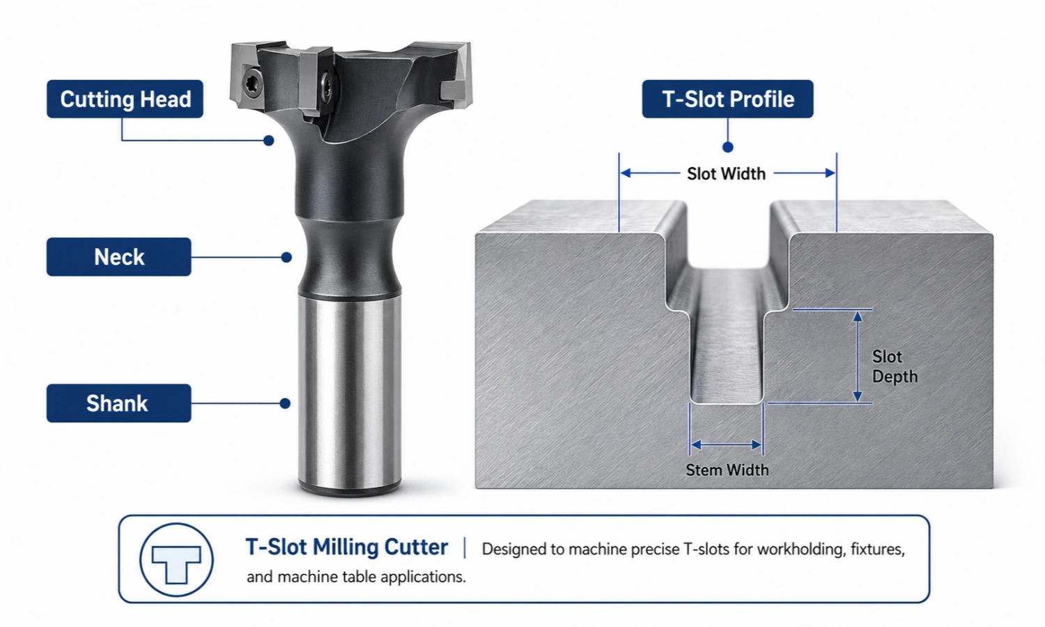
A T-slot milling cutter is a specialized milling tool used to machine the wider lower section of a T-shaped slot or undercut. It has a wider cutting head and a narrower neck, which allows the neck to work through the upper slot while the cutting edges machine the lower profile. For standard and customized solutions, see our T Slot Cutter product page.
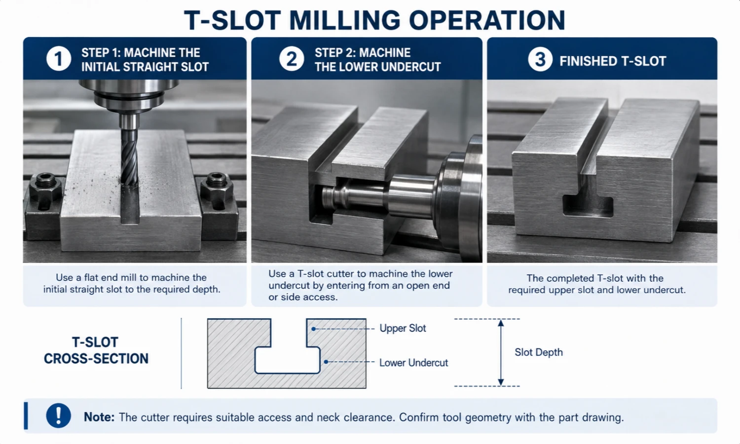
In a typical T-slot milling operation, the operator first machines an initial straight slot. Next, the cutter enters from an open end or another suitable access feature to machine the lower undercut.
What Is a T-Slot Milling Cutter Used For?
T-slot cutters are used when a component requires a relatively narrow upper opening and a wider lower undercut. This profile can retain T-bolts, nuts, fixtures, sliding components, or other locating and clamping elements.
Common applications include:
- Machine-table clamping slots
- Fixture plates and workholding systems
- Mold-base features
- T-bolt and T-nut retaining grooves
- Sliding or positioning components
- Mechanical assembly features
For example, a machine table may use T-slots so that vises and clamps can be moved and secured at different positions. Fixture plates can use the same principle to support flexible workholding.
The part geometry is the main deciding factor. If the feature only requires a straight groove without a wider lower undercut, an end mill or another slot milling tool may be sufficient.
T-Slot Milling Operation: How Does It Work?
T-slot machining usually involves preparing the upper slot first and then machining the lower undercut.
However, the cutter head should not be treated as if it can simply plunge through a narrow upper opening. The tool and part geometry must provide a suitable way for the wider cutting head to reach the lower machining position.
Step 1: Machine the Initial Straight Slot
First, machine an initial straight slot, sometimes referred to as the pilot slot. This opening establishes the upper part of the T-slot and provides the required path and clearance for the cutter neck.
A suitable flat end mill is commonly used to machine the initial straight slot before the T-slot undercut is cut.
The initial slot helps to:
- Establish the upper slot width
- Provide clearance for the cutter neck
- Prepare the path for the following undercut operation
If the T-slot is inside a closed feature, the machining plan must also provide a suitable entry area for the wider cutter head. The exact access method depends on the part geometry and cutter design.
Step 2: Machine the Lower Undercut
After preparing the initial slot and cutter access, position the cutting head at the required lower level. The tool then feeds along the slot and removes material from the lower section to create the T-shaped undercut.
At this stage, several conditions should be checked:
- Neck clearance
- Cutter reach
- Holder clearance
- Tool overhang
- Setup rigidity
- Chip evacuation
The tool must reach the required profile without the neck or holder contacting the workpiece. In addition, excessive overhang can reduce rigidity and make the operation less stable.
T-Slot Milling Cutter Dimensions: What to Check
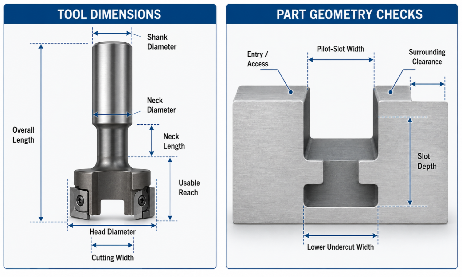
T-slot cutter sizes should not be judged by one diameter alone. Tool dimensions must work together with the actual T-slot geometry shown on the part drawing.
For this reason, it is useful to separate tool dimensions from part-geometry checks.
Tool Dimensions
| Tool Dimension | What It Helps Confirm |
|---|---|
| Cutting / Head Diameter | Helps determine the lateral extent of the lower undercut together with the tool path |
| Cutting Width | Determines the width of material removed by the cutting section |
| Neck Diameter | Determines whether the reduced section has sufficient clearance in the upper slot |
| Neck Length | Describes the length of the reduced-diameter neck section |
| Usable Reach | Indicates how far the cutter can reach into the required machining area; confirm this from the actual tool drawing |
| Shank Diameter | Determines compatibility with the holder or collet and affects setup rigidity |
| Overall Length | Helps evaluate total installation space but should not be treated as usable cutting reach |
| Corner Radius / Cutting Profile | Helps match the tool geometry to the required lower slot profile |
Different manufacturers may define some drawing dimensions differently. Therefore, always compare the terminology with the actual cutter drawing before making a final selection. Kennametal, for example, lists effective cutting diameter, neck diameter, overall length and usable length as separate specifications on its T-slot cutter data pages.
Part-Geometry Checks
| Part Geometry Check | Why It Matters |
| Pilot-Slot Width | Must provide appropriate clearance for the cutter neck |
| Lower Undercut Width | Defines the required finished lower T-slot profile |
| Slot Depth | Helps determine the required cutter position and reach |
| Shoulder Geometry | Affects cutter access and possible interference |
| Entry / Access Condition | Determines how the wider cutting head can reach the lower machining position |
| Surrounding Clearance | Helps prevent interference between the workpiece, cutter neck, shank, and holder |
This type of dimension interpretation is more useful than relying on a generic T-slot cutter size chart, especially for non-standard components.
Neck Diameter and Pilot-Slot Width
The neck must move through the upper slot without unwanted contact with the sidewalls.
If the available clearance is insufficient, the neck or surrounding tool structure may interfere with the workpiece. This can affect machining stability and surface quality.
However, there is no single generic clearance value that suits every cutter. Compare the workpiece drawing with the actual cutter drawing instead.
Neck Length and Usable Reach Are Different
Neck length describes the reduced-diameter section of the tool.
Usable reach refers to the practical reach available for the required machining geometry and should be checked separately. Overall length is also a different dimension and should not be used as a substitute for either value. Manufacturer product data commonly lists these dimensions separately.
Types of T-Slot Milling Cutters
T-slot milling cutters are available in several basic constructions. The purpose of this classification is to help users recognize the main tool types rather than select a product from material alone.
| Cutter Type | General Characteristic |
| HSS T-Slot Cutter | Uses high-speed steel as the cutting-tool material |
| Solid Carbide T-Slot Cutter | Uses carbide construction for the cutting tool or cutting section |
| Indexable T-Slot Cutter | Uses replaceable cutting inserts in the cutter body |
| Custom T-Slot Cutter | Uses drawing-specific geometry for a non-standard slot profile |
For example, indexable T-slot cutter systems use replaceable inserts and are usually specified by cutting diameter, neck diameter, usable length, and cutting depth.
Cutter construction alone does not determine the suitable choice. Workpiece material, cutter geometry, machining conditions, machine rigidity, coating requirements, and chip control should also be considered.
How to Choose the Right T-Slot Milling Cutter
The best starting point is the part drawing, not the coating or cutter brand.
First, confirm whether the cutter can physically access the slot and produce the required lower profile. Then review the workpiece and machining conditions.
Start with the Slot Geometry
Check the geometry in a practical order:
- Upper or pilot-slot width
- Lower undercut width
- Required slot depth
- Cutter reach
- Neck clearance
- Bottom or corner profile
- Entry condition
- Shank and holder clearance
These checks help determine whether the tool can enter the feature, reach the machining position, and cut the required profile without interference.
For a non-standard slot, compare the part drawing with the proposed cutter drawing instead of choosing the tool only by nominal diameter.
Confirm the Workpiece and Machining Conditions
Next, consider the actual machining environment.
Important information can include:
- Workpiece material and grade
- Material condition or hardness
- Required surface quality
- Coolant or dry-machining conditions
- Production quantity
- Cutter geometry
- Machine and holder condition
Material is important, but do not use it as the only selection rule. Review edge geometry, coating, chip evacuation, cutter construction, and machine conditions together for the specific application.
Check Setup, Holder, and Tool Clearance
T-slot milling takes place around an undercut and often within a confined machining area. Therefore, cutter access and setup clearance require careful attention.
Check:
- Tool overhang
- Holder clearance
- Workholding stability
- Machine rigidity
- Setup stability
- Chip evacuation
A shorter practical tool setup generally reduces unnecessary overhang, while adequate clearance prevents the holder or tool body from interfering with the component.
If a standard cutter does not match the required geometry, review a T-slot cutter for a drawing-specific profile.
T-Slot Milling Cutter vs Slot Milling Cutter
A T-slot milling cutter and a standard slot milling cutter do not create the same type of feature.
The most important difference is the lower undercut.
| Tool | Profile Created | Initial Slot / Access | Typical Use |
| T-Slot Milling Cutter | T-shaped profile with a wider lower undercut | Requires suitable initial slot and cutter access | T-slots, machine-table features, fixture grooves |
| Slot Milling Cutter | Straight slot or side groove | Does not use the same T-slot undercut process | General slot and groove machining |
| End Mill | Straight slots, pockets, shoulders, and profiles | Can be used to prepare the initial slot | General CNC milling |
If the feature has no wider lower undercut, a standard slot milling tool or end mill may be enough.
A T-slot cutter is needed when the drawing requires material to be removed below a narrower upper opening.
Common T-Slot Milling Mistakes
Good tool selection alone does not guarantee a stable T-slot machining process. Access, clearance, rigidity, and chip control can also affect the result.
Skipping the Initial Slot or Entry Planning
A standard T-slot cutter should not be treated like a conventional plunging end mill.
Before machining the undercut, prepare the required upper slot and confirm how the wider cutter head will reach the lower level. For a closed internal feature, this may require a dedicated access area or another planned entry method.
Selecting Insufficient Neck Clearance
The cutter neck needs adequate clearance inside the upper slot.
Insufficient clearance can cause:
- Neck contact
- Sidewall interference
- Heat buildup
- Unstable cutting
- Poor surface finish
Check the neck diameter against the actual upper-slot geometry before machining. Avoid relying on a universal clearance value.
Using Excessive Overhang or an Unstable Setup
Long tool overhang reduces setup rigidity and may increase vibration.
Use only the reach required by the part geometry. In addition, secure the workpiece properly and confirm that the holder has enough clearance around the component.
Ignoring Chip Evacuation in a Confined Groove
The lower undercut can create a confined area where chips are more difficult to remove.
If chips remain around the cutting zone, they may be recut or interfere with the tool. Therefore, chip evacuation should be considered when planning the machining strategy and coolant or air supply.
FAQ
Why is an initial straight slot required before T-slot milling?
The initial straight slot creates the upper portion of the T-slot and provides clearance for the cutter neck. It also establishes the path used before the lower undercut is machined.
However, the initial slot does not necessarily allow the wider cutter head to plunge vertically through the opening. The machining plan must provide suitable access for the cutter head.
Can a T-slot milling cutter plunge directly through the upper slot?
Not in a typical configuration where the cutting head is wider than the upper opening. The cutter head must reach the lower machining position through an open end or another suitable access feature determined by the tool and part geometry.
How do I choose the correct T-slot cutter size?
Start with the workpiece drawing and compare it with the actual cutter drawing. Check the upper-slot width, lower undercut geometry, neck diameter, cutter reach, entry condition, shank size, and available holder clearance before making the final selection.
Conclusion
A T-slot milling cutter machines the lower undercut of a T-shaped feature after the upper slot and suitable cutter access have been prepared. For standard sizes and custom manufacturing options, you can also visit our T Slot Cutter product page. Accurate selection depends on the relationship between the workpiece geometry and the actual cutter dimensions, especially neck clearance, cutting geometry, usable reach, entry condition, and holder clearance.