 Precision Milling Cutters,Cutting Tools for CNC Machining Every Material

This end mill selection guide explains how to choose a cutter by machining operation, end profile, tool material, flute count, coating, dimensions, and machine setup. Choosing the wrong tool can cause poor chip evacuation, chatter, rapid edge wear, dimensional errors, tool breakage, or an inconsistent surface finish.
This guide is written for machinists, process engineers, workshop managers, distributors, and buyers who need a practical starting point before selecting or requesting an end mill.
What Is an End Mill?
An end mill is a rotary cutting tool used for slotting, pocketing, profiling, side milling, roughing, finishing, and 3D contouring. Unlike a standard drill bit, it can cut with both the end and outside cutting edges.
Some center-cutting designs support ramping, helical entry, or limited plunging. However, the center geometry and entry method must suit the operation.
For a basic explanation, read what is an end mill cutter.
Quick End Mill Selection Guide
The table below provides practical starting directions. Final tool selection should still reflect the workpiece grade, cutter diameter, cutting depth, holder condition, machine rigidity, and chip-removal method.
| Machining Situation | Starting Tool Direction | Main Reason |
|---|---|---|
| Aluminum Slotting or Deep Pockets | 2–3 Flutes, Sharp Edge, Polished Flutes | More chip space and lower risk of chip packing |
| General Steel Side Milling | 4 Flutes, Strong Core, Heat-Resistant Coating | Balance of rigidity, edge count, and chip evacuation |
| Stainless Steel Side Milling or Finishing | 4–6 Flutes, Variable-Helix or Unequal-Pitch Geometry | Helps control vibration, heat, and unstable cutting |
| Heavy Roughing | Lower or Medium Flute Count, Roughing or Chipbreaker Geometry | More chip space and controlled cutting load |
| Finishing with Light Engagement | Higher Flute Count and Stable Geometry | More cutting contacts and improved surface consistency |
| Flat-Bottom Slots and Pockets | Flat End Mill | Produces a flat bottom and straight walls |
| 3D Contours and Mold Cavities | Ball Nose End Mill | Rounded end follows curved surfaces |
| Semi-Finishing and Stronger Corners | Bull Nose or Corner Radius End Mill | Radius strengthens the outside cutting corner |
| Deep Features with Limited Cutting Depth | Long-Neck Tool with Minimum Necessary Flute Length | Reduces deflection compared with an excessively long flute |
Use this matrix as the first filter. After that, confirm the end profile, tool material, flute count, coating, dimensions, and machine setup.
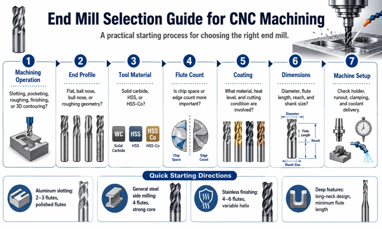
Step 1: Choose an End Mill by CNC Operation
The machining operation should guide the first decision because it determines the cutting direction, chip volume, engagement, and required surface.
Slotting
Full-width slotting creates a high chip volume because the cutter engages the material across its full diameter.
When cutting a full-width slot, prioritize chip space before increasing the flute count. Start with fewer flutes when chips are large or evacuation is difficult.
A suitable slotting tool normally requires:
- Enough flute space
- Reliable chip evacuation
- A center-cutting design when direct entry is required
- Short and stable tool overhang
- Edge strength matched to the material
For aluminum or other materials that produce larger chips, 2–3 flutes provide a practical starting point. For steel, the final flute count also depends on slot depth, radial engagement, cutter diameter, and coolant or air delivery.
If chips remain inside the slot, do not immediately increase the feed or change the coating. First check the flute space, cutting depth, air or coolant direction, and tool overhang.
Pocket Milling
Pocket milling may combine ramping, helical entry, side cutting, corner engagement, and bottom finishing.
Use a center-cutting end mill when the programmed entry requires cutting near the tool center. However, center cutting does not turn an end mill into a standard drill bit. The tool geometry and CAM entry strategy must support the movement.
Deep pockets also need reliable chip removal. Trapped chips can be re-cut, which increases heat and may damage the cutting edge.
When the pocket is deep but the actual cutting depth is short, choose a long-neck tool rather than an end mill with an unnecessarily long flute.
Side Milling and Profiling
Side milling loads the outside cutting edges. As a result, radial engagement, cutter rigidity, runout, and side-wall accuracy become important.
Use a flat end mill for straight walls and shoulders. Choose a bull nose or corner radius tool when the outside corner needs more strength.
For general steel side milling, a 4-flute tool provides a practical balance between edge count, core strength, and chip space.
For lighter radial engagement and stable finishing, 5–6 flutes can increase the number of cutting contacts. However, chip evacuation must remain stable.
Roughing
Roughing produces a high cutting load and chip volume. Therefore, the cutter needs enough flute space and an edge structure that can handle the engagement.
For traditional roughing, choose a lower or medium flute count when chip removal is difficult. Roughing or chipbreaker geometry divides chips into smaller sections and can reduce cutting resistance.
For dynamic or trochoidal toolpaths with lighter radial engagement, a higher flute count can become practical because each flute removes a smaller chip while the tool follows a controlled engagement path.
The CAM strategy, machine rigidity, holder condition, and tool geometry must work together. A high-performance roughing tool cannot compensate for weak clamping or excessive overhang.
Finishing
Finishing requires stable geometry, controlled runout, consistent cutting edges, and a tool profile that matches the required surface.
When radial engagement is light and chip evacuation remains stable, more flutes increase the number of cutting contacts and can support a smoother finish.
Before changing the cutter, inspect:
- Cutting-edge wear
- Holder accuracy
- Tool overhang
- Workpiece clamping
- Feed consistency
- Required corner shape
A worn tool or unstable holder can produce a poor finish even when the flute count is correct.
3D Contouring and Mold Machining
Ball nose end mills are widely used for curved surfaces, mold cavities, dies, and 3D finishing. Their rounded end follows complex surfaces more effectively than a flat cutting end.
Bull nose tools suit semi-finishing and profiling when stronger outer corners are required. Their corner radius strengthens the cutting edge while retaining a flatter central area.
For hardened mold steel, match the tool series to the actual workpiece hardness. A tool intended for materials up to HRC45 may use a different carbide grade, edge preparation, and coating from one designed for HRC60 or HRC65.
Step 2: Select the End Profile
| End Profile | Main Feature | Common Application |
|---|---|---|
| Flat End Mill | Flat cutting end with sharp outer corners | Slots, pockets, shoulders, flat surfaces, and side walls |
| Ball Nose End Mill | Fully rounded cutting end | 3D contours, curved surfaces, dies, and mold cavity finishing |
| Bull Nose End Mill | Flat end with rounded outer corners | Profiling, semi-finishing, mold machining, and stronger corners |
| Roughing End Mill | Serrated or chipbreaker cutting edges | High material removal and rough machining |
| Center-Cutting End Mill | Cutting edges extend across or close to the center | Certain ramping, helical entry, and pocket-entry operations |
Select the profile according to the feature being machined.
A flat end mill produces flat-bottom features and straight walls. A ball nose cutter follows curved surfaces. A bull nose tool strengthens the outside corner and often suits semi-finishing.
A center-cutting end mill can support specific entry movements, but its plunging capability depends on the center geometry, cutter diameter, workpiece material, and programmed toolpath.
For a more detailed comparison, read our end mill cutter types and uses guide.
Step 3: Choose Solid Carbide or HSS
Tool material affects rigidity, toughness, wear resistance, cutting-speed potential, and cost.
Solid Carbide End Mills
Solid carbide provides high rigidity, good wear resistance, and stable dimensional performance under suitable machining conditions.
Choose solid carbide when the application requires:
- CNC machining at higher cutting speeds
- Stable dimensional accuracy
- Steel, stainless steel, cast iron, or mold steel machining
- Longer production runs
- Consistent surface quality
- Small or medium cutter diameters with sufficient machine rigidity
Carbide is less tolerant of impact, excessive runout, unstable clamping, and severe vibration. Therefore, the machine and holder must support the tool.
For solid carbide options, view our carbide end mill cutter product page.
HSS and HSS-Co End Mills
HSS and cobalt HSS provide greater toughness and can tolerate vibration or interrupted cutting better in some applications.
Choose HSS or HSS-Co when:
- The machine runs at a lower spindle speed
- The setup has limited rigidity
- The cut is interrupted
- A larger custom cutter is required
- The order quantity is small
- Toughness matters more than maximum cutting speed
For a low-rigidity machine, HSS-Co may tolerate vibration and interrupted cutting better than solid carbide. However, carbide usually offers higher rigidity and wear resistance when the setup is stable.
The final choice should reflect the machine, workpiece, cutter size, cutting operation, quantity, and cost target.
Step 4: Choose the Flute Count
Flute count changes chip space, core strength, feed capability, and the number of cutting edges.
| Flute Count | General Selection Direction |
|---|---|
| 2 Flutes | Maximum chip space; useful when chip evacuation is the first priority |
| 3 Flutes | Balance between chip space, rigidity, and cutting-edge count |
| 4 Flutes | Common direction for general steel milling and side cutting |
| 5–6 Flutes | More cutting edges for stable side milling or finishing with controlled engagement |
Use 2–3 flutes when chip space is the main priority. This often applies to aluminum slotting, deep pockets, and operations that produce larger chips.
Use 4 flutes as a practical starting point for many general steel and side-milling applications.
Choose 5–6 flutes when radial engagement is lighter, the machine is rigid, and chip evacuation is already controlled.
More flutes do not automatically make a tool suitable for harder materials. In full-width slotting, too many flutes can trap chips and cause heat, edge damage, or tool breakage.
For a deeper explanation, read our end mill flute selection guide.
For a direct comparison, read 2 flute vs 4 flute vs 6 flute end mill.
Step 5: Choose Coated or Uncoated End Mills
Coating affects friction, heat resistance, wear resistance, material adhesion, and cutting-edge protection.
Use the following table as a selection direction rather than a fixed rule.
| Workpiece Direction | Coating or Surface Direction | Main Consideration |
|---|---|---|
| Aluminum and Non-Ferrous Materials | Uncoated, Polished, DLC, or Suitable Low-Friction Coating | Reduce adhesion and support chip flow |
| Carbon and Alloy Steel | TiAlN, AlTiN, or Suitable Heat-Resistant Coating | Heat resistance and edge protection |
| Stainless Steel | AlCrN, TiAlN, AlTiN, or Application-Specific Coating | Heat, wear, and cutting stability |
| Graphite and Abrasive Composites | Diamond-Coated Tools | Abrasive wear resistance |
| General Lower-Speed Applications | TiN or Uncoated Options | Lubricity and general wear protection |
Aluminum and Non-Ferrous Materials
For aluminum, start with a sharp edge, polished flute, and uncoated or low-friction surface.
A coating with high heat resistance is not automatically suitable for aluminum. If the surface increases material adhesion, built-up edge and poor chip flow may occur.
Steel
For carbon and alloy steel, TiAlN, AlTiN, TiSiN, or another suitable heat-resistant coating can protect the cutting edge.
As workpiece hardness and cutting temperature increase, carbide grade, edge preparation, and coating become more important.
Stainless Steel
For stainless steel, choose a coating and geometry that support heat control and cutting stability.
AlCrN, TiAlN, or AlTiN can provide useful starting directions, but the final choice should match the stainless grade, operation, flute count, coolant condition, and cutting load.
Diamond-Coated Tools
Diamond-coated end mills suit graphite, composites, abrasive non-ferrous materials, and other specific applications.
Do not use diamond coating as a universal choice for all metals. The workpiece chemistry and cutting conditions must be compatible.
The exact coating should match the carbide grade, tool geometry, workpiece grade, cutting operation, and coolant condition.
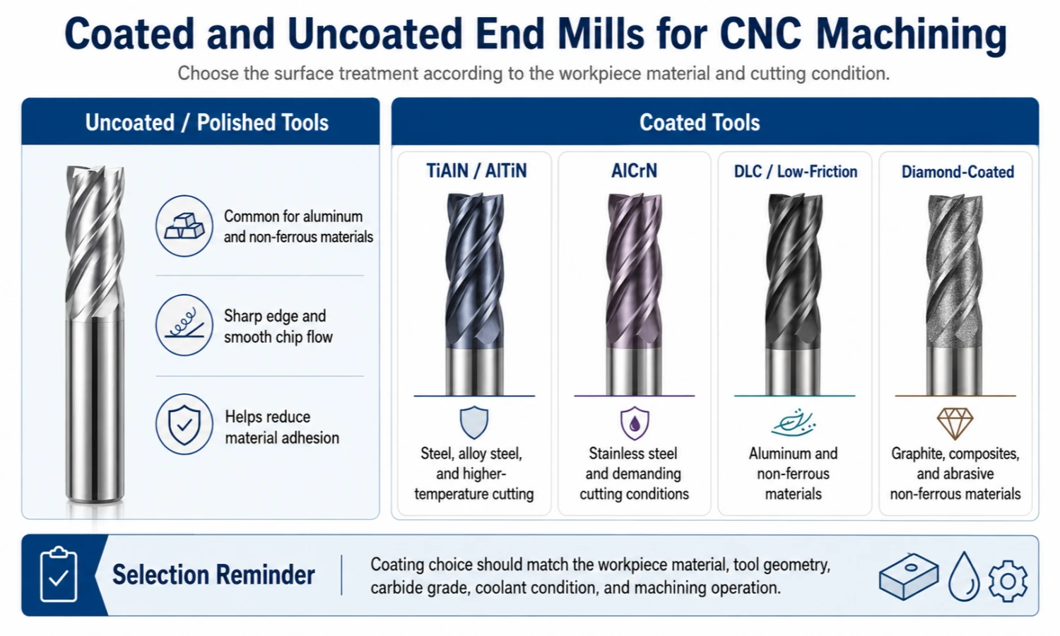
Step 6: Confirm Dimensions and Geometry
Cutter diameter is only one part of the tool specification.
Before ordering, confirm:
- Cutter diameter
- Flute length
- Overall length
- Shank diameter
- Required machining depth
- Tool reach
- Corner radius
- Helix angle
- Flute count
- Center-cutting requirement
- Dimensional tolerance
Use the shortest practical tool that reaches the machining area.
If the required reach is long but the cutting depth is short, choose a long-neck tool rather than an end mill with an unnecessarily long flute. A shorter cutting section can provide better rigidity.
Excessive flute length or overall length increases the risk of:
- Chatter
- Tool deflection
- Dimensional error
- Uneven wear
- Corner chipping
- Tool breakage
Choose a custom end mill when standard dimensions or geometry cannot reach the feature or meet the required diameter, corner radius, tolerance, coating, or application target.
Step 7: Check Machine, Holder, and Clamping Conditions
The correct end mill can still perform poorly in an unstable setup.
Tool Overhang
Long overhang reduces rigidity. Keep the tool as close to the holder as the machining depth allows.
Before changing the coating or flute count, check whether the cutter extends farther than necessary.
Holder Runout
Runout can make one cutting edge carry more load than the others. This causes uneven wear and may lead to poor surface finish, chipping, or premature failure.
Inspect the holder, collet, shank cleanliness, and tool seating when one flute shows more wear than the others.
Machine Rigidity
Spindle condition, holder accuracy, machine structure, and workpiece clamping all affect the result.
A rigid carbide tool cannot correct movement in the workpiece or holder.
Chip and Coolant Delivery
Air or coolant must reach the cutting area.
Poor delivery can leave chips inside deep pockets and slots. The tool then re-cuts those chips, which increases heat and damages the edge.
Workpiece Clamping
Movement at the workpiece can look like a tool problem.
Before changing the cutter, confirm that the fixture holds the part securely and that the toolpath does not create unnecessary vibration.
How Workpiece Material Affects End Mill Selection
Workpiece material remains important, but it should be considered together with the machining operation.
- Aluminum needs sharp edges and enough chip space.
- Carbon and alloy steel need stronger cutting edges and wear resistance.
- Stainless steel needs stable cutting to control heat and work hardening.
- Cast iron needs good abrasion resistance.
- Mold and tool steel require a tool series matched to the actual hardness.
- Titanium alloys require careful heat control and stable engagement.
For detailed material-based selection, read how to choose a carbide end mill cutter.
End Mill Selection and Setup Problems
| Symptom | Possible Cause | First Adjustment Direction |
|---|---|---|
| Chips Pack Inside the Slot | Too many flutes, insufficient flute space, poor chip evacuation | Reduce flute count, improve air or coolant delivery, and check flute length |
| Tool Breakage | Chip packing, excessive overhang, unstable holder, heavy engagement | Improve chip removal, shorten reach, check clamping, and reduce unstable engagement |
| Chatter Marks | Long overhang, weak setup, repetitive cutting forces | Shorten the tool, improve clamping, and consider variable-helix geometry |
| Poor Surface Finish | Worn edge, runout, unstable feed, unsuitable end profile | Inspect the tool and holder, stabilize the cut, and select the correct profile |
| Rapid Edge Wear | Wrong carbide grade, coating, or cutting condition | Match the grade and coating to material, hardness, heat, and operation |
| Corner Chipping | Sharp corner under heavy load, vibration, interrupted cutting | Consider a corner radius and improve setup stability |
| Aluminum Built-Up Edge | High friction, dull edge, rough flute surface, poor chip flow | Use sharp polished geometry and improve chip evacuation |
A machining problem can have several causes. Changing only the coating or flute count may not solve it.
Start with the setup, chip flow, tool condition, and engagement. Then evaluate whether the tool geometry needs to change.
Common End Mill Selection Mistakes
Choosing by Diameter Only
Two end mills with the same diameter may have different flute lengths, flute counts, end profiles, carbide grades, coatings, and applications.
Always review the complete specification.
Ignoring Chip Evacuation
Poor chip evacuation causes heat, chip re-cutting, built-up edge, chatter, and tool breakage.
This problem is especially common during full-width slotting, deep pocketing, and aluminum machining.
Using Too Much Tool Overhang
Excessive reach reduces rigidity.
Use the shortest tool that safely reaches the machining depth. If the feature is deep, consider a long-neck design with the minimum necessary cutting length.
Choosing More Flutes Without Checking Chip Space
More cutting edges improve feed capability and surface consistency when engagement is light and chip flow remains stable.
In deep slotting, however, excessive flute count can trap chips and damage the cutter.
Choosing a Coating by Name Only
A more expensive coating is not automatically better.
Match the coating with the material, carbide grade, geometry, coolant, cutting temperature, and operation.
Using One End Mill for Every Operation
A roughing cutter, finishing tool, slotting end mill, and ball nose cutter perform different jobs.
Choose the end mill according to the feature and machining stage rather than using one general tool for every operation.
FAQ
Can an end mill drill a hole?
Some center-cutting end mills support ramping, helical entry, or limited plunging. However, they should not automatically replace a drill bit.
Confirm the center geometry, cutter diameter, workpiece material, and programmed entry method before using an end mill for axial entry.
Should I choose carbide or HSS for a low-rigidity machine?
HSS or HSS-Co may provide more toughness and tolerance to vibration on a lower-speed or less rigid machine.
Carbide provides greater rigidity and wear resistance, but it needs a stable holder, controlled runout, and reliable clamping.
Why does an end mill break during slotting?
Common causes include chip packing, excessive flute count, too much tool overhang, unstable clamping, heavy engagement, and poor coolant or air delivery.
Check chip evacuation and setup stability before assuming that the carbide grade is the only problem.
When should I choose a variable-helix end mill?
Choose variable-helix or unequal-pitch geometry when repetitive cutting forces create chatter during side milling, profiling, or finishing.
The design can reduce vibration, but it still requires a rigid holder and stable workpiece clamping.
When should I use a long-neck end mill instead of a long-flute end mill?
Use a long-neck tool when the feature needs additional reach but only a short cutting section.
The reduced flute length normally provides more support than an unnecessarily long cutting edge.
What information helps when requesting a custom end mill?
Send the available tool dimensions, drawing, product image, workpiece material, machining operation, required feature, current tool model, quantity, and any existing machining problem.
You do not need to prepare every detail before contacting the supplier. Missing specifications can be confirmed during the quotation process.
Need Help Selecting the Right End Mill?
The right end mill depends on the machining operation, workpiece material, feature shape, required dimensions, machine setup, and surface-finish target.
Send us your drawing, tool model, required dimensions, product image, sample, or available machining information. With 16 years of cutting tool manufacturing experience, we can review the application and help confirm a suitable standard or custom tool direction.
View our standard and custom end mill cutter product page.
To discuss your application, email us at sales@cutterbest.com.